2

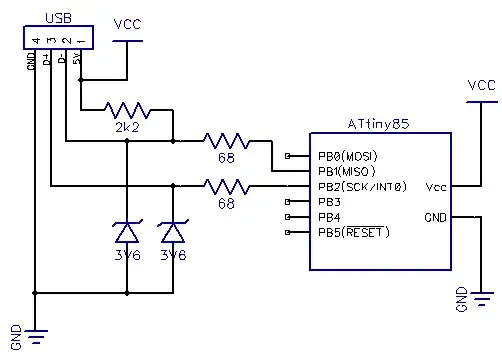
I'm planning to assemble a circuit this weekend; it is basically an attiny85 with a USB interface. The circuit is well known on the internet; see for instance this schematic:

Schematic

(Image taken from http://codeandlife.com/2012/03/03/diy-usb-password-generator/)

Now, currently I don't have any zener at home; I hope the local supply has them, but couple of times they didn't have even the most basic components, so there is some risk I will not be able to have them by the WE. So, here comes the question.

Can I substitute the two zeners with two blue leds? I know that the zeners have a steeper curve, so I will not have stable 3.6V (or better, a slightly lower voltage) on the lines, but... Is this really a problem for USB lines?

I read question LED as Zener: is this a good way to lower the BOM cost?, and there the main concerns were about the stability of the voltage (and in that case they were not an issue). Do you think there can be issues with USB? Did you already try that?

Thank you
frarugi87
  • 1,225
  • 1
  • 11
  • 18
  • 4
    The zeners are not strictly necessary, for a one off project you might get away without them. Using LEDs can help, bear in mind they are there to **protect** the micro, not to regulate anything: they basically short to ground any voltage above 3V6. – Vladimir Cravero Aug 31 '17 at 08:14
  • 3
    As Vladimir writes, the zeners are adding **extra** protection. So you can just leave them out **or** you could replace them with a string of diodes (in forward !). A standard 1n4148 has a forward voltage of around 0.6 V so if you use **6 in series** then you can use that instead of the 3.6 V zeners. That would give more predictable protection in my opinion. – Bimpelrekkie Aug 31 '17 at 08:33
  • 1
    The forward voltage of a LED is much less controlled than a zener diode's voltage rating. The zener diode will be tested by the manufacturer to guarantee that it meets the specification. For a LED I expect that it will only be checked that it lights up. **If** a LED is cheaper and **if** your application can work with the LED's unpredictable forward voltage and speed is not an issue (a LED might be slower than a zener) then yes, you can save cost and use an LED. But in general you should not blindly replace a zener with a LED, only do that when circumstances allow it. – Bimpelrekkie Aug 31 '17 at 08:39
  • That application is a low-speed HID keyboard replacements. An application running at higher speed could run afoul of the significant capacitance of those LEDs. – glen_geek Aug 31 '17 at 10:32
  • 1
    Thank you all for the comments. I'm answering all of them singularly because I can't cite more than one person in each. @VladimirCravero, I think the zeners are there to protect the USB rather than the micro (micro is powered at 5V, the USB specs have a lower voltage on D+ and D-) – frarugi87 Aug 31 '17 at 11:26
  • @Bimpelrekkie As I wrote in the other comment, I think the protection is for the USB. Anyway 6 4148s for each wire are a bit too many. The reason to change them is not for having a cheaper BOM, but because maybe I cannot find the zeners in the shop – frarugi87 Aug 31 '17 at 11:27
  • @glen_geek My application is not a low-speed keyboard, but is still a low speed USB peripheral (otherwise the attiny85 will not be able to cope with the traffic on the USB data line) – frarugi87 Aug 31 '17 at 11:35
  • 1
    *I think the protection is for the USB* No, the protection is to protect the ATtiny against too high voltages on the USB **datalines**. Without the zener diodes the only protection consists of the 68 ohm resistors + the ESD protection in the ATtiny. By itself that often **is enough**. Only if you want a better (more robust) protection then the zeners are needed. – Bimpelrekkie Aug 31 '17 at 12:04
  • Remember that you have control of the ATtiny, while the user has control of the USB cable. Who knows what the user could do with it. – Vladimir Cravero Aug 31 '17 at 12:20
  • @Bimpelrekkie Can you give me some references about these high voltages? AFAIK (see for instance [here](https://electronics.stackexchange.com/questions/190592/why-does-usb-have-vcc-5v-and-high-3-3v)) the bus on the USB has a max value of 3.6V; this seems to be supported by the fact that circuits using V-USB on attiny running at 3.3V (e.g. this [this](http://codeandlife.com/2012/01/25/avr-attiny-usb-tutorial-part-2/)) do not have zeners on its pins... And in the first part of the tutorial he says "While USB power is 5V, the data lines require 3.3. Some computers tolerate 5V logic but not all" – frarugi87 Aug 31 '17 at 12:54
  • 1
    Maybe you're thinking that these high voltages are "normal for USB" and that the zeners must be there for "normal operation ? That is not the case !!! Under ideal, normal conditions these zeners would **never turn on**. All the ICs connected to USB will just put "normal" voltages on the datalines as described in the USB specification. The function of the zeners is to **protect** against non-standard events like ESD discharges and faulty devices. These are rare events and the ICs should be robust against these events but some designers want extra protection just to be safe. – Bimpelrekkie Aug 31 '17 at 13:29
  • 2
    Actually, the OP is correct, the Zeners are there to protect USB host from ATtiny85 driving 5V on data lines. – Ale..chenski Aug 31 '17 at 17:07
  • @Bimpelrekkie sorry if I'm still on this topic, but believe me I'm genuinely trying to understand. I was pretty sure about that since a lot of sources confirmed what I told you; the USB specs state that the max voltage on the data lines is 3.6V, and the attiny generates 5V on its pins (no dedicated USB peripheral here). consequently in the codeandlife tutorial I linked they used a 3.3V powered attiny without zeners or a 5V one with zeners. Does this mean the 3.3V does not require ESD protection? Moreover you say that they never turn on. But when the attiny sources current, the voltage is ... – frarugi87 Sep 01 '17 at 07:34
  • ... 5V, so the zener starts conducting with a current (5-3.6)/68 = 25mA (or a bit less due to the internal attiny resistance). I know that for ESD protection you usually put zeners (or better, tvs) diodes on USB lines, but I hardly think this is the case of a DIY-level circuit like the tons of circuits derived from this schematic. Every 5V design I saw had them, and every 3.3V design didn't. These reasons make me think that the zeners are there to lower the output voltage. Do you have some reference to your view? Again, I'm just trying to understand, not provoking or something like this – frarugi87 Sep 01 '17 at 07:38
  • 1
    @AliChen Oh, OK, then I misunderstood. I was assuming that the ATtiny would "properly" drive the USB datalines. It is now obvious to me that it is not capable of doing that. Indeed then the protection **is needed** and it does not protect the ATTtiny (what I suggested) but it protects the USB datalines from the 5V which the ATtiny tries to drive them with. – Bimpelrekkie Sep 01 '17 at 07:39
  • Yes, the zeners are needed to limit the voltage that the ATtiny puts on the USB datalines. Back to your question, could I use LEDs ? I think the answer is no as the LEDs don't have a well defined forward voltage and they might also not be fast enough resulting in short 5V spikes on the USB datalines and that is what we're trying to prevent with the zeners. – Bimpelrekkie Sep 01 '17 at 07:42
  • Question for OP: what do you mean under "issues with USB"? If you are trying to make one device for your home use, then go ahead, use whatever you find in your drawer. If you are thinking to make a commercial device out of this, the bit-banging USB likely won't pass any serious tests, eye diagram, crossover points, jitter, frequency, everything will fail. What is your goal then? – Ale..chenski Sep 01 '17 at 16:41
  • I'm a bit worried about the LED capacitance, please check if it is lower than the zener. Shouldn't cause trouble on low-speed USB but better safe than sorry. – bobflux Sep 01 '17 at 20:17
  • 1
    @peufeu, although the LEDs are not usually characterized for their capacitance, this article, http://www.edn.com/design/led/4368392/An-LED-s-intrinsic-capacitance-works-in-a-650-mV-LRC-circuit quotes it as 50 pF, while small Zeners have about 500 pF. The SE also quotes it as 50 pF, https://electronics.stackexchange.com/a/86720/117785 – Ale..chenski Sep 01 '17 at 20:53
  • Nice one! So the LEDs may actually work better than zeners... – bobflux Sep 01 '17 at 20:59
  • @peufeu, not really. For a nice LS signal you need to limit the signal edge slew rate. So a Zener with 500 pF and 100 Ohms on driver side (68 +25 GPIO) gives you ~50 ns rise time, which is below the 75 ns minimum requirement (with 300 ns max). But you also need to receive something, that's why USB has a special business branch for making specialized USB PHYs. – Ale..chenski Sep 01 '17 at 21:16
  • Thanks for the info, I just learned something interesting thanks to you ;) – bobflux Sep 01 '17 at 21:20
  • @AliChen I know that no commercial product can use this solution. Moreover many microcontrollers with integrated USB are even cheaper than attiny85, so for any commercial product I'd go wiht a dedicated USB peripheral. This is only for home, so I had to go with an "easier" solution, and I tried this. I just wanted to avoid frying my PC's USB controller because of using this circuit, so this is the purpose of this question – frarugi87 Sep 04 '17 at 10:12

2 Answers2

4

Yes, for a USB Low-Speed applications 3-V LEDs can be used in this schematics.

Actually, in this case these Zeners serve some USB functionality, and their main purpose is not ESD protection but voltage limiting. Reason is that this MCU is powered from +5V supply directly, without any 3.3V regulator. At 5V the ATtiny I/O drivers have about 25 Ohms, and would drive hard to 5V, which is not what USB needs nor likes. The signals should be limited to 3.3 - 3.6 maximum in order to not to fry the USB host. That's why the schematics uses the insane 68 Ohms in-series resistors, and 3.6V Zeners. The data signal clipping don't need to be precise, so 3-V LEDs will be okay, and even add some fun illuminating USB traffic.

In the past the USB interface used to be tolerant to direct contact with +5V. With modernization in silicon technology and integration of USB physical interfaces (PHYs) into low-voltage 22 and 14 nm silicon (where transistors are barely 1-V tolerant), the requirement to hold 5V on data lines was eliminated. So the USB lines better be protected from DIY devices like this ATTiny projects.

Ale..chenski
  • 38,845
  • 3
  • 38
  • 103
  • Thank you for your contribution. Luckily I found the zeners (and since I was in a hurry I did not experiment with the LEDs). When I have time I'll also try with LEDs on the two pins and a USB hub to experiment if it is ok to use them. For the moment, thank you! – frarugi87 Sep 04 '17 at 10:14
0

You really shouldn't need the Zeners at all. Their purpose seems to be only voltage clamping. They can help clip some ringing if someone uses a out of spec cable, but they generally shouldn't be needed.

It appears the processor is running directly from the USB nominal 5 V power. Perhaps the Zeners are to clip the 5 V to the 3.3 V level required of the USB signals. I don't know about the ATiny parts, but the Microchip PIC 18s with a USB peripheral deal with the USB signal voltages directly. Some even have a LDO in them so that the part can run straight from the USB power.

The fact that the circuit doesn't include a bypass cap between Vcc and ground at the processor throws suspicion on the whole thing and put everything else in the same publication, web page, or whatever, in question. In other words, this was clearly not done by somebody competent. Run away.

Olin Lathrop
  • 310,974
  • 36
  • 428
  • 915
  • 3
    Olin, This is an example of bit-banging low-speed USB, where computing enthusiasts skipped even on 3.3V regulator. So the GPIO pins are running from 5-V rail, and therefore 3.3V clipping is needed. One shouldn't confuse this ATtiny with PIC18, where they have a dedicated USB PHY bonded to dedicated pins, all perfectly certifiable to USB standards. – Ale..chenski Sep 01 '17 at 20:44
  • @AliChen in fact skipping the 3.3V regulator is not used because of speed issues (the attiny does not support 16.5MHz at 3.3V, only at 5V; the first versions using an attiny2313 used it out of specs - 12MHz @ 3.3V is not supported) – frarugi87 Sep 04 '17 at 10:07
  • @frarugi87, thanks for the clarification, duly noted. – Ale..chenski Sep 04 '17 at 14:55