simulate this circuit – Schematic created using CircuitLab
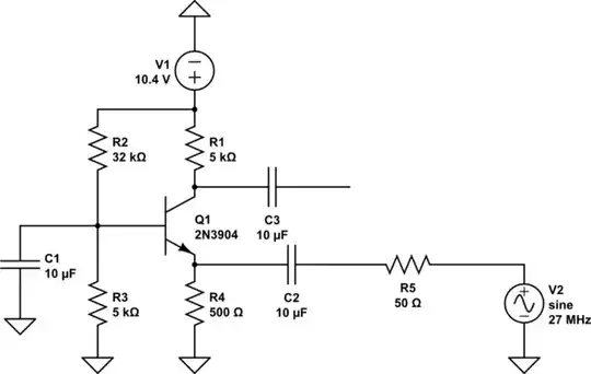
Here's a little schematic I built for my 27MHz colpitts oscillator, which outputs approximately 120mVpp. Since the common base is less dependent on frequency, is less prone to distortion and has high gain I chose it over the CE amp. I used several different transistors in the place of 2n3904. Even some soviet ones with GBP pf 800-1000 MHz. I simulated the schematic in LTSpice and got this result.

The output is 2.4Vpp, so the gain is 20. And here's the first confusing part: So far I've learnt that the gain of CB amp is
A=Rc/re
Rc= 5000
re=25/Ie
Ie, in the DC state, according to the same simulation is about 1.44mA, so re should be about 17 ohms. The gain in that case should be about 300. I am not expecting this kind of gain in reality however it is a huge jump from 20 to 300. I do suspect that on high frequencies there is some effect that I am not aware of. The CB configuration should basically eliminate the Miller effect, and I don't know what else might cause the drop in gain.
Anyways it's not where the problem ends. After building the amp on the desk the gain was even smaller than expected 20. The output Vpp was around 300 mV, a bit more than 2 times larger than the input (every transistor behaved like that, even high GBP ones). I should also note that the same high GBP transistors performed much better when used in CE configuration (around 2Vpp), although with quite a bit of distortion, which was why I decided to use CB.
I disconnected the signal source to check if the DC biasing etc was done correctly, and the voltages on each node were around the same as in the simulation.
I decided to make a frequency domain analysis in spice and here's what I got:  This is with the 2N3904. I suppose that transistors with higher GBP will have different curve (although not sure about that). Anyways the gradual roll-off is very visible.
Since I used the transistors in CE configuration effectively I highly doubt that the transistor is the problem here. I suppose the problem lies within the schematic itself, although I fail to find it. The question is: why does the schematic behave like it does in real life? Also how can one fight the gradual roll-off if it is possible at all?
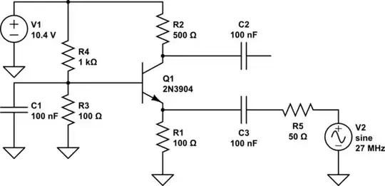
UPDATE:
After reading the suggestions, reduced the effect of low pass filters by reducing the resistor values, which also increased emitter current. Ended up using this circuit, which gave a gain of about 5. It's probably very suboptimal but, it worked better than the last one. The output was about 700 mVpp with input of 120 mVpp.