Inductive voltage regulation
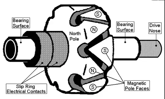
The traditional bicycle dynamo's (see note) output voltage will vary roughly proportional to speed. If this problem is not addressed the lamps - its intended load - will be very poor at low speeds and the bulbs will blow at high speed. The solution is to design the system - dynamo and lights - as a complete package with enough series inductance built in to the dynamo to regulate the terminal voltage.
Note: Technically the bicycle generator is an alternator since it outputs AC. Dynamos output DC.
simulate this circuit – Schematic created using CircuitLab
Figure 1. Standard dynamo arrangement showing internal series resistance and inductance.
The impedance of an inductor is given by \$ Z = 2 \omega L = 2 \pi f L \$. This shows that the impedance is proportional to the frequency which, of course, is directly related to the speed of the bike. If designed correctly the lamps will turn on to a reasonable brightness at quite low speed and will be noticeably brighter at high speed but without blowing the lamps - the reason being that the inductors and lamps form an L-R voltage divider.
Setup: two wires are soldered to dynamo on one end, on other end they are soldered to 5 Ohm resistor. True RMS multimeter is measuring AC voltage across the resistor.
Since the specification is 3 W at 6 V we can calculate from \$ P = \frac {V^2}{R} \$ that optimal load is given by \$ R = \frac {V^2}{P} = \frac {6^2}{3} = 12 \; \Omega \$.
If that works you might wish to chart power as a function of velocity. It should be fairly constant.
There are various articles on the web from folks who have tried to figure out the characteristics of various alternators.
Figure 2. Comparison of various brands and models as a function of speed. Note that the load is not specified. It can be assumed that it is the same 2.4 + 0.6 W front and rear bulb configuration. Source: Myra-Simon.