19

What is the fast and elegant way to generate PWM without a Microcontroller to control a servo motor? With potentiometer or other ways to control the duty cycle with fix period.

  • sorry about the mess, I want to control a hobby servo.
pstan
  • 911
  • 2
  • 10
  • 18
  • Do you really mean controlling a motor as part of a servo control system, or are you asking about controlling a "hobby servo"? See addition to my answer. – Olin Lathrop May 24 '12 at 22:08
  • 1
    Why do you want PWM? PWM is often just a way for a micro to approximate an analog control function. If what you really want is an analog voltage or current, there are probably much better ways to do it. – The Photon May 24 '12 at 23:17
  • 2
    @ThePhoton If he's controlling a hobby servo, PWM is what is required as a control signal. – Nick Johnson May 25 '12 at 00:04
  • If you drop the fixed period requirement, a delta-sigma oscillator would be a very simple solution. I've seen implementations with a single opamp and a handful resistors/capacitors. This assumes you're not talking about RC-servo's. – jippie May 25 '12 at 07:06
  • 1
    @jippie - What's a delta-sigma oscillator? I know a delta-sigma ADC needs an oscillator, but I always assumed it was a common thing, since it isn't really part of the converter itself. – stevenvh May 25 '12 at 08:52
  • Frankly, the restriction to not use a micro is silly. A micro is definitely the easiest and smallest way to solve this problem. A PIC 10F220 can do this. All you need it the pot, the 10F220 which comes in SOT-23 package, and a bypass cap. Two parts and only a few square mm to make a pot to hobby servo pulse converter. A micro is just another chip. After you're done, paint it black and put it in a box and nobody will know nor need to care what is inside. – Olin Lathrop May 25 '12 at 11:45
  • @Olin - that would have been my answer, if microcontrollers were allowed! And with the ATTiny5 instead of the PIC, of course :-) – stevenvh May 25 '12 at 11:48
  • Very simple 555-based circuits can be found in any of the first 4 hits for "555 servo" (I did not cehck beyond the 4th). – Wouter van Ooijen May 25 '12 at 12:31
  • @Wouter - Come on, Wouter, you're spoiling it for us... ;-) – stevenvh May 25 '12 at 12:48
  • @stevenh - A love uControllers, but the 555 is a legend (more than the 709 or 741, maybe the 723 comes close). One day I want to build a CPU using 555 555 chips. Preliminary investigation hows that this is insane but still doable. – Wouter van Ooijen May 25 '12 at 13:06
  • @Wouter - when I was in college my brother and I laid out plans to make a mechanical CPU, using small metal balls for the bits. Was never built... – stevenvh May 25 '12 at 13:25
  • @stevenvh: sorry, that was a typo which I thought I had corrected. I meant a delta-sigma *modulator*. The https://en.wikipedia.org/wiki/Delta-sigma_modulation looks a bit complicated, but in practise it can be a pretty straightforward circuit. – jippie May 25 '12 at 17:01

5 Answers5

31

I recommend the (GASP!) 555 Timer in "astable" mode. You'll find everything you need in the link, but I copied them here just for you!

Astable mode gives you a variable PWM frequency, and allows for an adjustable duty cycle as well (high-time and low-time equations in the link).

The circuit:

555 Timer, astable mode

Note: I'd add an electrolytic cap across Vcc (positive lead) and GND (negative lead) to reduce the effect of dips in power supply voltage.

The PWM frequency:

Output frequency of 555 Timer in astable mode

Some defense for my answer compared to others in this post. Most other answers require an intermediate waveform to generate a variable PWM signal, such as the common triangle wave/comparator method. I don't see much point in constructing triangle wave generator (a significant circuit in-and-of itself) just as an intermediate step to solve your problem.

The 555 is a great analog chip and does just what you need. I wish people didn't hate on them as much.

kevlar1818
  • 624
  • 5
  • 6
  • 3
    I like 555s, but I think that @supercat is right in that a single 555 won't be able to give you a fixed-frequency, variable-duty-ratio signal. C gets charged through R1+R2, and discharged through R2. If you increase R2, you will increase both on and off times, and therefore the period. If you increase R1, you only increase the on time, but also the period. If you increase C, you will increase all times, including the period. You need two 555s. One, in astable mode, that will determine the period, triggering a second one, in monostable mode, that will determine the duty ratio. – Telaclavo May 24 '12 at 22:41
  • 6
    "You'll find everything you need in the link". No. That's not the proper way to answer. Provide the details here. – stevenvh May 25 '12 at 06:43
  • 1
    I don't hate the 555, I just wish people wouldn't refer to them as the *best* solution for *everything*. A single 555 is not the best way to control a hobby servo. – stevenvh May 25 '12 at 06:51
  • A hobby servo does not need a fixed frequency signal, 20-30 Hz will do just fine. – Wouter van Ooijen May 25 '12 at 12:34
  • [Heres](http://www.kpsec.freeuk.com/555timer.htm#dutycycle) how you can have a longer off time than on. – Dean May 25 '12 at 13:29
  • 1
    @stevenvh I am not going to take the time to draw the 555 Timer circuit and write the equation for PWM frequency in terms of component values when both are VERY clearly defined in that link. In any Stackexchange forum, it has never been considered bad etiquette to "link" someone to the answer somewhere else on the web, provided a simple explanation of what the link says. I mentioned the mode of the 555 and that it provides a variable PWM frequency. I see nothing wrong with my answer. – kevlar1818 May 25 '12 at 13:32
  • 1
    @Telaclavo - You are correct; you can't vary the duty cycle and keep the frequency constant. However, as WoutervanOoijen mentions, you don't need a rigidly fixed frequency to run a servo. Varying the duty cycle probably creates about a 10-20% (rough estimate) wobble in the pulse frequency, which should be accurate enough for most servos. And then again, you don't really need to adjust the duty cycle to control a servo anyways. – kevlar1818 May 25 '12 at 13:37
  • 2
    I've seen many short answers, leaving the rest to a link, deleted. The reasons have been explained often: links die, and this site wants to be self-sustaining. I shouldn't have to follow a link, the information should be here. Copying an image here may make already a world of difference. – stevenvh May 25 '12 at 13:40
  • 2
    @stevenvh You let me know when Wikipedia dies. Even if it does, as Dean showed with his comment above, the 555 is (was) so ubiquitous it would be difficult not to find an old book, small blog, or hobby website with info about them. – kevlar1818 May 25 '12 at 13:44
  • 2
    That's not the point. There's no way to tell which links will die and which won't. Assume none is immune to it. In the time you spent posting your last comments you could have posted an image. I do so in my answers very often, and from the rep it gets me I know users appreciate it a lot. (85 "nice answer" badges) – stevenvh May 25 '12 at 13:53
  • There you go @stevenvh. Just for you. – kevlar1818 May 25 '12 at 14:22
  • 1
    Fine. I think you also should add the equation for the duty cycle, so that users know which resistor should be a potmeter. – stevenvh May 25 '12 at 14:27
9

Triangle wave. Comparator. Control threshold. That's the basic way to do it.

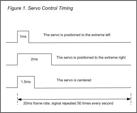
If you want to control a hobby servo, however, this is not the best way. The duty cycle varies between 5% and 10% (1ms to 2ms pulse width in a 20ms period), which is short, and most likely you want to control it with some precision. On a 5V\$_{PP}\$ triangle you have to vary the comparator's threshold between 4.5V and 4.75V. Any deviation and you won't be able to control the servo over its full range. That requires precision components. Also, the triangle wave generator needs 2 opamps, and then there's the comparator.. There's a better way.

enter image description here

First generate a 50Hz square wave. Most simple way:

enter image description here

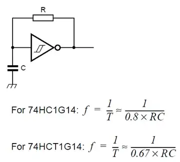
For the 74HC1G14 a 250k\$\Omega\$ resistor and a 100nF capacitor will give you a 20ms period.

Feed the square wave into a MMV (Monostable MultiVibrator). You can do this with an LM555, or use a logic device like the 74HC123A. If you use the latter the pulse time is defined by \$R_{EXT}\$ and \$C_{EXT}\$:

\$ T = R_{EXT} \times C_{EXT} \$

Time in \$\mu\$s, R in k\$\Omega\$, and C in nF.

To get a pulse width varying between 1ms and 2ms you use C = 100nF, and R = 10k\$\Omega\$ in series with a 10k\$\Omega\$ potmeter.

I could have done this with two LM555s, but I'd need more external components.

edit (about microcontrollers)
I agree with Olin (see comments) that excluding a microcontroller is short-sighted (Olin said "silly"). There was a time when developing for a microcontroller was complicated, but today that's no longer true. You can also have a programming interface for a few euros. The solution would then look so easy that no non-controller solution can compete with it: you take an ATTiny5 (Olin takes a PIC10F220) in a SOT23-6. Connect a decoupling capacitor to the power connections and the potmeter to the ADC input. That's it! 3 (three) components. Converting the ADC reading to a pulse width output is so easy that it's almost ridiculous, even for a beginning programmer.

Once you get started with them you'll find that microcontrollers often offer a more simple and more flexible solution than with other ICs or discrete components.

a note
From your other question I see that you do use microcontrollers. Why do you want to avoid them here?

Joel Spolsky
  • 547
  • 1
  • 5
  • 17
stevenvh
  • 145,145
  • 21
  • 455
  • 667
  • What's the way to get a triangle wave? – m.Alin May 25 '12 at 08:05
  • 1
    @m.Alin - If you want a very clean triangle [this](http://www.falstad.com/circuit/e-triangle.html) is the proper way. But the inverter input in my oscillator also approximates a triangle, though the slopes are really exponentials. – stevenvh May 25 '12 at 08:08
  • 1
    locally speaking , 555 is cheaper than 74HCT1G14 in here. +1 BTW.\ – Standard Sandun May 25 '12 at 12:36
  • @sandun - did you count the external components too? – stevenvh May 25 '12 at 12:40
  • yes I did. Is true when this is a hobby project specially. The chances are high that 74HCT1G is completely absence in OUR local market. – Standard Sandun May 25 '12 at 12:52
  • @sandun - Single gate logic was introduced rather recently, so it may not have penetrated everywhere yet, especially not the hobby market. There was a need for logic which was much smaller than the common 14 or 16 pin devices. Think smartphones. Many devices exist in packages less than 1mm\$^2\$. – stevenvh May 25 '12 at 12:55
  • 3
    @stevenvh " If you want a very clean triangle this is the proper way." By your logic this is completely unacceptable. Please include this in your very informative and complete answer. – kevlar1818 May 25 '12 at 13:34
  • @kevlar1818 - agreed. Fixed. – stevenvh May 25 '12 at 15:03
  • @stevenvh Sorry for being silly. I use uC a lot and I wonder how people generate PWM before we have uC. – pstan May 26 '12 at 09:03
  • 2
    @pstan - If your specs aren't too high you'd probably use the 555 circuit. It's far from perfect: the frequency varies with the duty cycle, and the control isn't linear. The [triangle generator](http://www.falstad.com/circuit/e-triangle.html) + comparator solves those drawbacks. – stevenvh May 26 '12 at 09:09
  • I think the main reason for using dedicated hardware is either for cost savings, or for fun. where cost savings are lagely around how many microcontrollers still are atleast around 1€ and often the cheap ones are much harder to get since they aren't in local store for example the PIC10F220 already costs close to €1 and either has to be bought in large amounts from some company sourcing parts(to make sure the shipping cost doesn't increase the price by a to big % or you would have to take a lucky chance at aliexpress and hope they actually send you something that atleast acts like the real one – TeD van Loon Apr 29 '23 at 17:31
8

The Ye Olde Phashioned way to make PWM with analog controlled duty cycle is to compare the analog control signal to a triangle wave. You make a triangle wave generator that runs at the desired PWM frequency. This is fed to the negative input of a comparator and the analog control signal to the positive input. The result is either full high or full low, but the duty cycle is linearly proportional to the control signal. Early class D audio amps worked on this principle, for example.

In a lot of cases the PWM didn't need to be super linear, so the triangle wave doesn't have to have perfectly straight edges. Allowing them to be a little exponential can simplify the circuit.

Added:

Mark Rages pointed out that when you say "servo motor", you could be referring to the little position-controlled hobby motors used on model planes and the like. My answer applies to controlling a motor assuming you have a analog voltage proportional to how hard you want to drive the motor. It does not apply to these "hobby servos". Those aren't controlled by PWM in the common sense of that term, but by the width of pulses that usually need to be from 1 to 2 ms repeated every 20 to 50 ms or so. If this question is really about hobby servos, then it should be fixed to make that clear.

Olin Lathrop
  • 310,974
  • 36
  • 428
  • 915
  • While this does accomplish the task, it's important to note that @pstan wants to drive a servo, and so having a function generator in his implementation probably won't be very portable. – kevlar1818 May 24 '12 at 20:44
  • 1
    Servo motor duty cycles are generally quite low, like 10% or less. And the servo uses pulse width directly, not average value, so it's better to use a circuit that decouples pulse width from repetition rate. – markrages May 24 '12 at 20:49
  • 1
    @kevlar: I rechecked my answer and I still don't see mention of a function generator in there. All I said was you need a triangle wave or something close enough. You certainly don't need a function generator to make one of those. – Olin Lathrop May 24 '12 at 20:50
  • @Markrages: Huh? Motors see the average of a pulse train if it is fast enough. A few 100 Hz is plenty good enough in that regard for most motors. The servo part is accomplished by the control scheme, which the OP didn't ask about. It seems he already has a analog level proportional to how hard the motor is to be driven. – Olin Lathrop May 24 '12 at 20:58
  • @Markrages: It just occured to me that you are talking about hobby servos, which want a 1-2 ms pulse every 20 ms or so? Your comment makes some sense in that light, but the OP didn't mention hobby servos at all. – Olin Lathrop May 24 '12 at 21:00
  • @OlinLathrop The OP specially said "servo", and surely you can assume someone asking a question like that is a hobbyist, thus you can probably put hobby in front of the servo name. – Kellenjb May 24 '12 at 21:20
  • @OlinLathrop I made an assumption about hobby servos. It would be better to ask for clarification when "servo" is used by itself. – markrages May 24 '12 at 21:33
  • @Kellen: Actually it didn't occur to me at all until Mark's comment. "Servo" has a meaning in electrical engineering, which relates to a control system. I realize that some hobby motors with servo control built in are incorrectly called "servo motors", but that's not what I think of first. People need to use the correct term. – Olin Lathrop May 24 '12 at 22:01
  • "aren't controlled by PWM in the common sense". How is it different? It's just the control range which is limited to 5%-10% duty cycle. It's not PPM, for instance. – stevenvh May 25 '12 at 09:21
  • @steven: You can argue hobby servos require PWM, but usually when you talk about PWM, the average level of the signal is the meaningful part. In hobby servos, only the width of the positive pulse is meaninful. The negative pulse width can vary widely, and has no effect as long as it is within some range. – Olin Lathrop May 25 '12 at 11:40
  • Yes, I saw the "20 to 50 ms or so" in your answer. I read that 20ms is a typical (recommended?) value. I don't know what the circuit inside a servo looks like, so I have no idea what it tolerates. But you're right, if the period can vary so wildly it ain't proper PWM. – stevenvh May 25 '12 at 11:45
  • @OlinLathrop and yet a google search for "Servo" brings up tons of hits and product recommendations for the so called "hobby servo". Just like I said in my meta answer, we should not limit the terms that people use if they are indeed common terms. You may not think it is the proper term, but google sure seems to think it is commonly used. http://meta.electronics.stackexchange.com/a/1139/319 – Kellenjb May 25 '12 at 12:59
4

The simplest way to generate a PWM signal is to feed a sawtooth wave or triangle wave into one input of an analog comparator and a control voltage into the other. If one can't get a pure triangle wave, one may reasonably approximate one by passing a square wave through an RC filter such that the output of the filter swings between roughly 1/4VDD and 3/4VDD, and then scaling the control voltage going into the comparator so that the a control voltage which should yield 0.01% duty cycle will be translated to the lowest voltage of the filtered square wave, and the control voltage which should yield 99.99% duty cycle will be translated to the highest voltage of the filtered square wave. This will yield a pulse width that isn't quite linearly proportional to amplitude, but is close enough for many purposes. Adjusting the RC filter so that its output has a narrower swing, and scaling the control voltage to match, will improve linearity but my increase noise sensitivity.

supercat
  • 45,939
  • 2
  • 84
  • 143
  • 1
    And this is exactly what the NE555 circuit does as proposed by kevlar1818... – Cees Meijer May 24 '12 at 20:50
  • 2
    @CeesMeijer: The poster asked for a variable duty cycle and fixed period. I don't know of any way to use a single 555 to convert a control voltage into a fixed-frequency variable-duty cycle wave. It could serve very nicely to generate a triangle-ish wave to feed into a comparator, though. – supercat May 24 '12 at 20:58
  • It's been 20 years since I built this circuit, so I had to look this up. And indeed you are right. I used an external trigger to get a constant frequency. You could use a second 555 for that though. – Cees Meijer May 30 '12 at 09:05
3

I recommend using a low-voltage (BiCMOS) power supply control IC like the UCC3803. The operating frequency can easily be set with a simple R and C, and the duty cycle control easily done with a potentiometer. It will operate on a 5V rail.

excerpt from TI UC3842 data sheet

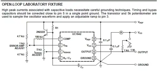
The UCC3803 is pin-compatible with the UCx84x series of PWM controllers. If you want to do easy PWM, you can use the above schematic, omitting R1, the 2N2222 and the 5k ISENSE adjust pot (just tie pin 3 to ground). You probably can also omit the two 4.7k resistors in series with the error amp adjust pot and go directly to Vref and Gnd, or use an explicit voltage divider if adjustment isn't necessary. (You didn't specify if you need to easily change the duty cycle).

The IC is capable of driving around 1A of current. (If your servomotor has a PWM input, this is a moot point.)

Adam Lawrence
  • 32,921
  • 3
  • 58
  • 110
  • "may need an external driver to actually power the motor". Are you sure? I always thought the PWM input is just a low-current signal level. For power a servo has a third connection. – stevenvh May 25 '12 at 11:36
  • Also, I just remember the duty cycle is only 5 to 10%. That can' be the proper way to supply power. – stevenvh May 25 '12 at 11:42
  • This is nice. But still counts lots of external components. – Standard Sandun May 25 '12 at 12:45
  • Looks more like an UEMIG: Unnecessary EMI Generator. :-( – stevenvh May 25 '12 at 12:51
  • It also seems to need a minimum 10V input. Maybe not the best choice... – stevenvh May 25 '12 at 14:09
  • @stevenvh OP didn't specify anything about his motor - PWM, input voltage range, nothing. My solution is nothing more than an easy way to make an adjustable PWM output which happens to be used in millions of switching power supplies. – Adam Lawrence May 25 '12 at 14:25
  • First, I appreciate that you think out of the box to come up with original solutions. But OP added that it's for a hobby servo, and if you didn't know already you can read in the other answers what kind of signal they need. I doubt this is a very good solution. – stevenvh May 25 '12 at 14:31
  • @stevenvh The OP should be explicit with his requirements (volts and PWM) - that should't be the burden of the repliers. I've revised my answer to be compatible with an (assumed) 5V motor. – Adam Lawrence May 25 '12 at 14:59