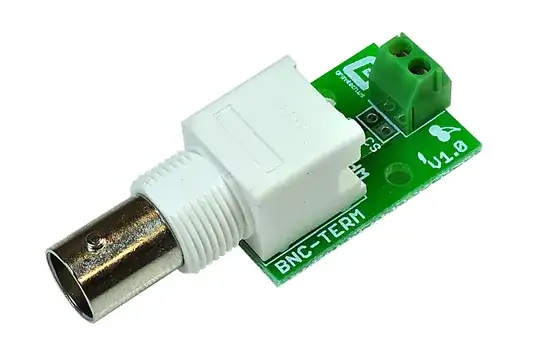
Solution with highest signal integrity is:
- Cut BNC-BNC cable in half, strip it down
- Solder the braids to the boards' ground plane on the back (remove soldermask with blade first)
- Solder coax center conductor to input pin
Less annoying solution:
Since half the pins on the analog input connector seem to be ground, I would use a 16 pin 0.1" dual row female header soldered on the edge of a bit of blank PCB. Only solder the ground pins, let the other ones hang in the air. Now drill 2 holes in the PCB, install BNC connectors which will be properly grounded, and connect the signal conductors to the header with short wires.
EDIT
The enormous CMRR of "110dB typical" rejects differences in voltage between "local ADC ground" and "signal common mode voltage or remote source ground" but the signals have to be between 0V and AVCC, that's not negotiable. Most likely the 8 unused pins are connected to the ground plane. We've been having a little bit of a misunderstanding because to me it is obvious that the pins should be grounded, so I had trouble understanding why you think they are not.
For example, someone would plug a ribbon cable on the connector, in this case it is nice to have one wire for ground between each signal line, as this prevents crosstalk.
If the cable is shielded (like shielded twisted pair) then the shield becomes useless except for very low frequencies unless it is grounded at both ends. The shield can be grounded through a capacitor at one end though, to block low frequency currents in it while allowing it to shield at HF.
So, I wonder what you really mean...


