2

I'm using Interlinks 30-49649 Force sensitive sensor(FSR), the FSR resistance decrease when the force applied increase.

the FSR datasheet has the following graph.
enter image description here

Looking into the graph, a 10K resistor for RM would be the best option, as using other resistors shows that there isn't a big variation in voltage.

Below you can see the FSR resistance variation with the force.

Graph showing Resistance variation

Now my question is this, The output will go into a 10-bit ADC, and i feel that this signal would not give a good result in the ADC as the variation is still small and maybe linearizing the signal will give better resolution and accuracy, but i read also that linearizing the signal is useless when using an adc, so amplification is a must, but how does linearization affect the sensor?

L. Lt.
  • 388
  • 1
  • 4
  • 17
  • It depends a lot what range you want to measure. 1000g is a lot of force! Using a 100K resistor gives a 0-3V difference for 0-200g, which is still huge. – David Aug 19 '17 at 11:52
  • What i know is that i need the full range, i agree that 1000g is a lot but thats what the customer wants, my problem is that the customer didn't specify the resolution and accuracy, he doesn't know much about sensors so these details doesn't concern him, but i do want to give the best resolution and accuracy that i can have from the sensor. – L. Lt. Aug 19 '17 at 12:04
  • You would need to know some transfer function of this FSR, then you can compute the suitable resistor and inverse transfer function. – Marko Buršič Aug 19 '17 at 12:20
  • That's not "g" as in gravities for acceleration. That's "g" as in grams. So, that is up to one 1kg. That's not what I'd call a lot of force. – JRE Aug 19 '17 at 12:29
  • 2
    If I were messing with this, I'd probably use the 3k and use a reference voltage of a little over 2V for the ADC. That gets you an almost linear response over most of the range, and makes maximum use of the ADC input range. – JRE Aug 19 '17 at 12:36
  • Have a look . http://www.openmusiclabs.com/learning/sensors/fsr/index.html – Marko Buršič Aug 19 '17 at 12:45
  • A log-responding linearization would seem to apply. Could be done with a diode. Temperature coefficient of both the diode and the sensor then becomes important. – glen_geek Aug 19 '17 at 13:37

2 Answers2

2

You may not be able to do what you want. When the sensor is just one leg of a resistor divider, then you get the maximum resolution when the sensor has the same resistance as the other resistor of the divider. Such a setup can deal with the 0 to infinite range of the test resistance, but measurement resolution drops off with the ratio between the two resistors.

To decide whether the setup is good enough, you have to first decide what the resistance range of the sensor will be during intended operation. Then you have to decide what resolution you want to measure the resistance with.

You want the fixed resistance of the divider to be such that it is the same ratio from either end of the range. For example, let's say you care about resistances from 1.2 kΩ to 340 kΩ. That's a ratio of 283. The midpoint in ratio-space is the square root of that from either end. That is 16.8. The midpoint is then (1.2 kΩ)16.8 = 20.2 kΩ. You should get the same thing by applying the midpoint ratio from the high end: (340 kΩ)/16.8 = 20.2 kΩ.

To find the worst case resolution, do the math. Compute the voltage into the A/D for either extreme. Then work backwards to see what resistance would yield one A/D count more to the middle.

Using the above example, you have a 20.2 kΩ pullup and the test resistor to ground. At 1.2 kΩ, the output voltage of the divider is 0.0561 of the reference. Let's say you are using a 12 bit A/D. The A/D output will be 230. You therefore have a resolution of 1 part in 230, or not quite 8 bits, at the ends of your range.

That's the resolution you can measure resistance at. Now work that back to see what pressure delta that represents at both the low and high ends of the range.

If this isn't acceptable, then you have to do something different. For example, you could use a higher resolution A/D, or a different topology altogether.

Olin Lathrop
  • 310,974
  • 36
  • 428
  • 915
  • Why did you do the square root of the ratio to find the midpoint? is it because the resistor divider ratio variation logarithmic? – L. Lt. Aug 21 '17 at 06:55
  • @L.L: To keep the *ratio* from center to either end the same. That minimizes the worst case error. – Olin Lathrop Aug 24 '17 at 20:51
  • i understood this part, i meant what is the math behind this? why is the square root the midpoint in the range? – L. Lt. Aug 25 '17 at 05:15
  • @L.L: If the multiple is the same from the low end to the midpoint as the midpoint to the high end, then applying the the multiple twice (the square) gets you from the low to the high. Therefore, this multiple is the square root of the ratio of high to low. – Olin Lathrop Aug 25 '17 at 22:44
1

You can use this high-end multi-range ADC:

schematic

simulate this circuit – Schematic created using CircuitLab

The one on the left is the cheap version, the one on the right is the "luxury" version, so I wil go with that.

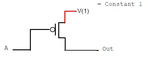
  • Set the output to logic 1. This charges the capacitor.
  • Acquire voltage. This gives an accurate measurement if FSR resistance is low and inaccurate measurement if FSR has high resistance.
  • Set the output pin to high-Z
  • Acquire the voltage every 5µs, then after the first few acquisitions, you can go slower, like powers of two, 5,10,20 µs etc
  • Stop when the voltage is close to VCC/2

Let's say the ADC reading was A=1.000 at the beginning, and it is A=0.470 after 4 ms...

\$ A = e^{-t/RC} \$

\$ R = - \frac{t}{C ln A} = 53000 \Omega\$

Accuracy depends on microcontroller clock (good thing a quartz oscillator costs peanuts and you already have one anyway) and the RC discharge kinda acts like a magnifier, allowing to accurately measure high resistor values.

The cap should be good quality, like C0G.

There are many similar cheap tricks to use a microcontroller ADC. For example you can expand this by using an AC voltage on your resistor (just output a square wave on a pin), then filter this with a lowpass filter (ie, a cap) and by varying the frequency, you can vary the strength of the signal to be measured. Amplify it with an opamp, which can be fixed gain and won't clip since you control signal amplitude, then acquire. This also gets rid of DC offsets and other annoyances.

There's also this one:

schematic

simulate this circuit

Set the desired pin to output logic 1 and the others to high-Z, and you can choose the upper resistor in your divider, giving you several ranges. Mind the output resistance of the pin, which won't be lower than 30 ohms and is temperature-dependent, though. But if you calibrate your sensor with known weights, that'll take care of it.

bobflux
  • 70,433
  • 3
  • 83
  • 203