50

I have a Panasonic RX-ES29 boombox with a type C plug (ungrounded). I sometimes hear a relatively loud snap/pop sound in the right speaker of my headphones while I completely plug them into the headphones jack of the boombox when it's on. There's a little buzz when the tip of the jack is inserted but the loud pop comes when the jack is completely inserted. My headphones are Audio Technica ATH-AVC500.

I tried to capture that sound using a male to male cable, but after playing the captured one, it's not as loud as the one I hear by physically connecting headphones to it. You can see the pictures I took from Audacity here and there.

enter image description here

enter image description here

Audacity doesn't detect it as an audio clipping, but it looks like it is by the pictures that I linked above.

One of the strange things about it is that it does not always occur, I mean it's not always there; like sometimes when something discharges near your finger. I tried to unplug and plug several times just after hearing the loud sound but it's gone, exactly like when a charged object is discharged and it needs some time to charge up again.

I'm very curious to know an explanation for this weird behavior.
Transistor
  • 168,990
  • 12
  • 186
  • 385
Sepp A
  • 563
  • 1
  • 4
  • 6
  • 13
    Panasonic seems to have absolved themselves of complaint for their design shortcoming. Manual says: **Reduce volume before connection. Plug type: 3.5 mm stereo** – glen_geek Aug 10 '17 at 19:45
  • 1
    The reason why the captured sound is not _as_ loud is that you reach the limit of the recording device. – yo' Aug 11 '17 at 09:09
  • 1
    @yo' Actually, I captured it as a microphone because my computer doesn't have a Line In. – Sepp A Aug 11 '17 at 20:08

4 Answers4

49

That's a "DC pop". A sound engineer dies somewhere every time you make one!

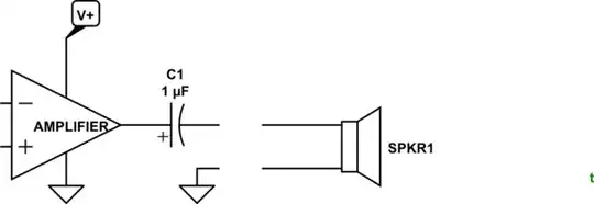
schematic

simulate this circuit – Schematic created using CircuitLab

Figure 1. Amplifier output and disconnected speaker.

Amplifiers fed from a single-rail supply hold their output at 1/2 supply when quiet. If the speaker was connected directly to the amplifier output there would be a DC current flowing through it continuously, heating it up and biasing the cone off centre. It would have limited travel in that direction and, so, would clip and distort much earlier than it should.

By adding a de-coupling capacitor the DC is blocked but the AC can pass through.

If the amplifier is switched on without the speaker connected as shown in Figure 1 the left side of C1 will be pulled to V+/2. The right side will follow suit. When the speaker is plugged in a current will flow to ground until the right side reaches zero volts.

A similar result will occur when plugging an audio source into a device with a DC blocking capacitor on the input.

Note also that if the devices are disconnected while powered up the capacitor may discharge back to power-up conditions due to capacitor leakage or PCB leakage.


schematic

simulate this circuit

Figure 2. Adding a discharge resistor.

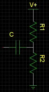
As noted in the comments, we can add a discharge resistor to the circuit so that after some delay the right side of C1 has fallen to 0 V. Since this resistor will provide additional loading to the circuit we don't want to make it any lower than necessary.

One approach to finding a solution would be to decide how long we can wait for discharge.

enter image description here

Figure 3. Capacitor discharge curve. The capacitor discharges by 63% per RC time period.

A handy rule of thumb is that the "time constant" of an RC circuit is given by multiplying R and C. \$ \tau = RC \$. After \$ \tau \$ the voltage will have decayed by 63%. After \$ 3\tau \$ it will have decayed by 95% and \$ 5\tau \$, 99%.

Let's say we want to incorporate a resistor that will discharge by 99% in 1s: \$ 5 \tau = 1\;s \$ so \$ \tau = 0.2 \;s\$. In our example C1 is 470 µF so \$ R = \frac {\tau}{C} = \frac {0.2}{470\mu} = 420 \; \Omega \$. This is more than ten times the speaker impedance so it won't load the circuit too much.

Transistor
  • 168,990
  • 12
  • 186
  • 385
  • 31
    +1 for "*A sound engineer dies somewhere every time you make one!*" – Trevor_G Aug 10 '17 at 19:36
  • 2
    @SeppA Add a high-value resistor (like 1000 ohm) on the output jack from signal to ground. Might help keep the sound engineer population alive. – glen_geek Aug 10 '17 at 19:55
  • 6
    I was thinking "add a resistor" but I'm sure there is an unpopulated resistor footprint on the output, because a bean counter looked over the schematic and asked "we sure won't pay for that!" – bobflux Aug 10 '17 at 20:23
  • 1
    Possibly a stupid question but I just want to make sure... What does adding the resistor solve here? Another path to ground correct? Thus preventing that surge to audio device when the cap is uncharged? If so, what affect does the size of the resistor have? How did @glen_geek know to use 1000 ohm? Thanks! – Capn Jack Aug 11 '17 at 14:34
  • 2
    @CapnJack Resistor value isn't critical...small enough to prevent the coupling capacitor from self-discharging...but much larger than the headphone impedance, so it doesn't suck a lot of power from the final amplifier. – glen_geek Aug 11 '17 at 15:02
  • @glen_geek The last part makes sense to me, thanks. But would you mind going a little further in detail about the capacitor self-discharging if the resistor is too small? Possibly with some example numbers? For example, how would using a 100 ohm resistor cause self discharging where a 1k would not? And am I right in saying the placement would be after the capacitor and before the OC in the schematic above? – Capn Jack Aug 11 '17 at 15:09
  • 2
    @CapnJack That output coupling capacitor will be electrolytic, perhaps 470uf...an imperfection is self-discharge. A rough model would add a parallel large resistor to account for its self-discharge, perhaps 100k. The pop gets attenuated by the voltage-divider ratio. A 100 ohm resistor across the jack would attenuate a pop 999 times (a 1k resistor only 99 times). – glen_geek Aug 11 '17 at 15:45
  • @CapnJack: See d'update. – Transistor Aug 11 '17 at 16:13
  • @glen_geek Oh I think I get it now. The 100k is a theoretical resistor right? We're not actually placing it. It models the capacitor's impedance. So using a 1k resistor we're essentially making a voltage divider and now the output voltage is ~100x less than what it was before. But wouldn't this affect the volume of our output? – Capn Jack Aug 11 '17 at 17:09
  • @Transistor That clears up so much thank you! Just trying to figure out how the resistor doesn't end up attenuating the volume overall. Assuming the cap is 100k~ impedance then your 420 in series would give a voltage divider effect that results in a vout of ~220 less than expected, correct? Wouldn't that be nearly in-audible? – Capn Jack Aug 11 '17 at 17:14
  • @Transistor Also when you say "This is more than ten times the speaker impedance so it won't load the circuit too much.", why does that matter? Thanks so much so far btw. Love this site and people like you on it. – Capn Jack Aug 11 '17 at 17:15
  • @CapnJack: Well what would happen if you made the resistor *equal* to the speaker? Half the power would go into the resistor and half to the speaker. It may overload the amp to the point of overheating or distortion (depending on many other constraints). The 1/10 additional load in the example will waste 10% of the power. For a particular application this may be alright or not. – Transistor Aug 11 '17 at 19:59
  • @Transistor Thank you so much for your answer. I'm curious to know why didn't they fix this issue rather than recommending to reduce volume before connection? What does exactly reducing the volume do to prevent the pop? and do these pop noises damage the speakers of headphones? – Sepp A Aug 12 '17 at 11:19
  • @Transistor I found this Answer very helpful and I have a possibly related question which I've asked [here](https://electronics.stackexchange.com/questions/377541/quieting-headphone-pop-would-it-work-to-put-a-discharge-resistor-in-a-custom-do). I'd appreciate it if you could take a look. Cheers. – Spiff May 31 '18 at 21:08
16

"Exactly like when a charged object is discharged and it needs some time to charge up again."

That is exactly what you are hearing. The output is AC-coupled through a capacitor to the headphones to block any DC component of the signal. With the headphones first unplugged the capacitor had one side open circuit so it stays discharged.

When you plug in the headphones, the capacitor needs to charge to whatever the DC voltage is before it... and POP.. you hear that current as it energizes the speakers in the headphones.

Unplug and plug again, the capacitor retains that charge a long time.

Note the same effect can be heard through the speakers when first turning on an amp if special measures are not taken to limit it.

This can be significantly corrected by adding a largish resistor to ground across the outputs of the amp on the right of the cap.

ADD By the way, the reason you only hear it on one speaker is likely to do with the way jack plugs work. The right speaker is likely attached to the tip of the plug, as such, as you plug it in it first makes contact with the left channel, charging that cap, then makes contact with its own channel charging that, too. By the time the left speaker contact makes its connection, its output capacitor is already charged.

mike65535
  • 1,481
  • 2
  • 16
  • 26
Trevor_G
  • 46,364
  • 8
  • 68
  • 151
  • +1 for _adding a largish resistor to ground across the outputs of the amp on the right of the cap_. – TimB Aug 10 '17 at 22:10
  • 1
    Largish is a good technical term, simply meaning between > and >>. So, with an 8 ohm speaker, 80 - 800 ohm resistor. Given it is a discharge circuit, whatever is lying around would work ok. Audiophiles would calculate it... – MikeP Aug 11 '17 at 20:59
  • 1
    @MikeP - in my experience, audiophiles would be unlikely to have an amp that runs off a single supply rail, and therefore have a very small DC component, so probably wouldn't bother. I mean, adding that resistor in there turns the whole thing into a high-pass filter anyway, which means *some of their signal is being lost!* – Jules Aug 11 '17 at 22:40
  • @Jules - "Audiophiles" (or perhaps "audiophools" as the case may be) would probably object to having a cap in there at all. Thus, no high-pass and no "loss". But that also means that their speakers can receive DC offsets that don't do squat except heat up the voice coils. "Power compression" is when a speaker heats up, which increases resistance, and therefore draws less from a voltage-source amplifier for the same setting. – AaronD Aug 12 '17 at 01:48
  • 1
    @Trevor: The standard as I know it is Tip=Left, Ring=Right, and Sleeve=Ground/Return. So it would be the left channel per the standard that charges both caps. However, it's possible that the OP's wiring is crossed somewhere. It's hard to tell that without a test track or other known recording; the sound stage is simply mirrored and still makes sense. – AaronD Aug 12 '17 at 01:51
  • @Trevor Thank you but I don't understand what's the origin of the sawtooth/triangle noise and why does it continue for ever until the plug is fully inserted? – Sepp A Aug 12 '17 at 11:28
6

@Transistor is right, however there is a tiny subtlety here...

Jack connectors short everything to ground when you plug them in. When you slide it in, the various metal bits of the jack and the plug make contact in every possible combination before the jack finally settles into position.

There's a little buzz when the tip of the jack is inserted

I would guess that in this position, both channels are shorted together, and the opamps on both outputs go in and out of short circuit protection, or misbehave in other weird ways that cause this buzz.

When they go into protection, most likely the output goes to ground, so the cap ends up discharged... or maybe they clip to the rail, who knows.

And when the jack slides into place, both opamps come out of protection and snap their outputs to Vcc/2, therefore you hear something loud.

The weird thing is that your pop is the wrong polarity. It should be positive. Either your soundcard inverts polarity, or what I said above is true, and there is some weird clipping/instability going on as the outputs are shorted during insertion.

bobflux
  • 70,433
  • 3
  • 83
  • 203
  • I captured it as a microphone, not a Line In and the cable that I used was very short and not a high-quality one. Maybe these have something to do with the weirdness you described. – Sepp A Aug 12 '17 at 11:24
0

A common problem I have found with earlier amplifiers is the large DC offset at the headphone jack on amplifier switch on. This was due to the capacitor coupled output stages on amps that only has a single rail for the power amplifier. AS a result the output is floating above ground and has to be blocked by a fairly large value capacitor. Amplifiers like the great Marantz 1060 is one suce amplifier that has destroyed a few headphones of mine in the past including more recently a pair of AKG K550's. The capacitor used to block the DC is fine for the loudspeakers that are anything as low as 4 ohm and rated in the tens of watts. But this DC into a modern fragile headphone voice coil can result in a burnt out driver. The only easy was s mentioned here, is to block the DC post the headphone attenuator with a capacitor of around 220-470uF. At this value there should be very little noticeable low frequency rolloff into a headphone >16 Ohms.