12

I am working on an Android ADK project. I am looking for a way to detect the locations of chess pieces on a board (8x8). I was looking at things like NFC but It looks too expensive. Is there a different technology that I should consider. I need something that world be able to read the full state of the board at any time. For example some of the pieces might get knocked over and once they are set back up I need the locations. To explain this further, in a touroment chess game if the pieces are moved to the wrong location and neither player notices the game will continue. So I need to record the game even if the position is impossible based on the game rules.

I just want to be pointed in a general direction of what technology to look at.

theJosh
  • 223
  • 2
  • 7
  • "In a tournament chess game if the pieces are moved to the wrong location and neither player notices the game will continue". I'm curious. The chess rules say so? (Actually, it makes sense, because -if there's no one else watching-, how could they not continue, if none of them notices?) – Telaclavo May 22 '12 at 11:09
  • @Telaclavo I can confirm, that's happened to me in a tournament. There was no apparent solution at my low level of play. – Stephen Collings Mar 21 '13 at 12:25

6 Answers6

14

First idea: RFID. One tag (very cheap) underneath each piece. Each tag should identify which type of piece it is (out of {6 white}+{6 black}=12 different types). One transceiver circuit and a 1-to-64 multiplexer for the whole board. Also, 64 little antennae, each one underneath each board position. The transceiver operates at a very low RF power (you should find the optimum one, experimentally). By changing the multiplexer connections, you scan all 64 positions, and read the IDs of the tags (if any) present over each one of them.

I've never used the ICs it talks about, but this document might help you implement the RFID multiplexer (which will be the most challenging part, together with its careful layout).

Second idea: distinguish each piece type by its unique magnetic permeability. To each piece, you will add a certain mass at its bottom. This extra mass will be the same for all 32 pieces (so that the users feel comfortable with them). Each extra mass will be the sum of two masses: a "magnetic" mass, plus a "compensation" (non-magnetic) mass. The only purpose of the compensation mass will be to make the total extra mass equal for all types of pieces. You need to distinguish 12 different types of pieces. Each type of piece must have a magnetic mass with a unique magnetic permeability, \$\mu\$. You will probably choose materials with a high \$\mu\$, but there are plenty of materials you can choose from, each with a different \$\mu\$ (see one table here).

Underneath each board position, you will need to wind several turns of wire (so that the diameter is almost the side of the square). You will have 64 coils. Again, use a 1-to-64 multiplexer, to connect only one of them to an inductance meter. The difference, now, is that the multiplexer does not need to deal with RF. You can tie one node of all coils together, and use 64 analog switches (very cheap), to direct, as I said, one coil to the inductance meter. The circuit will have to determine, in the shortest possible time, what is the self inductance measured at each one of the 64 coils. It doesn't need much accuracy. It just needs to determine 13 different possible values for L (that is less than 4 bits!). You can experiment with methods in the time domain (e.g., applying a constant voltage, and measuring the slope of the current), or in the frequency domain (e.g., trying to quickly seek what's the resonant frequency, with a certain added capacitor). To attain those 12 different values for L, you can play with different permeabilities, and different dimensions for the magnetic material.

Since you have to scan 64 positions (measure 64 self inductances) in a reasonable time, I would probably go for time-domain approaches. For instance, if you allow yourself 1 second to read the whole state of the board, you have 15.6 ms for each inductance measurement. Challenging, but doable.

If speed ends up really being the bottleneck, you could make your system 8x faster, if you include 8 analog front ends, instead of one. Each front end would be devoted for each row in the board. That way, you could measure 8 self inductances simultaneously (giving you 125 ms for each measurement, and you would still have a whole board state in 1 second). I'm sure that one MCU, even with a single ADC (with 8 channels), would be enough.

This could be (without all details) the schematic for each front end (which could be one for the whole board, or one for each row, as mentioned), and a way to quickly estimate self inductances \$L_1\$ to \$L_N\$ (N being 8 or 64). The common node for the coils would be the top one, and the control signals for the analog switches are not shown, for simplicity. TS would be constant, and VX sampled at TS would be used to compute the self inductance. TG would be just slightly longer than TS.
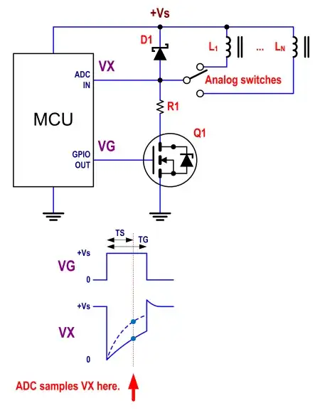
Idea 2

Benefit of this second idea: no RF involved. However, you need to build your own "tags", with different permeabilities.

Telaclavo
  • 4,867
  • 19
  • 28
  • Thank you. Your first idea seem to be the way to go. I like the creativity of you second idea. It might be better for a commercial product where the pieces could be custom made. However, I'm just doing this for fun. – theJosh May 21 '12 at 16:32
  • @theJosh Even after having answered, there's a sentence in your question that still confuses me. The one "For example some of the pieces might get knocked over and once they are set back up I need the locations" doesn't make much sense to me, because if pieces are knocked over, it should be the memory of your system who should tell the user where to place the pieces, and not the other way around. I interpreted that sentence as: you want the system to be able to read any arbitrary board's state, without relying on history, and I discarded simpler answers with that in mind. – Telaclavo May 21 '12 at 18:18
  • @theJosh (continued). If that was not the case, davidcary's solution would be simpler. – Telaclavo May 21 '12 at 18:19
  • The problem with the first idea is that it requires a fairly short range for the RFID. If the range is too much (more than a square) then it becomes more difficult to sense the proper position of the piece. Not impossible (I hope), just much more difficult. –  May 21 '12 at 20:27
  • @DavidKessner Right, that's why I said that he would need to find the optimum RF power experimentally. The distance from antenna to tag is much shorter than the distance between two adjacent squares, so it should be doable. – Telaclavo May 21 '12 at 20:33
  • I added more info about what l would want if the pieces got knocked over. – theJosh May 22 '12 at 04:04
4

I've seen many electronic chessboards that have a hole drilled in the center of each of the 64 squares, with a simple photodetector under each hole, which gives only 1 bit -- "nothing here", or "a piece of some kind is covering the detector". This requires (a) some memory and code to remember the old configuration of the board, and to track which piece moved where, and (b) something special to handle pawn promotion. This can detect which squares are occupied and which squares are open at any time, but not the full state of the board.

davidcary
  • 17,426
  • 11
  • 66
  • 115
  • 1
    Clever! Very simple hardware backed up by logic! – clabacchio May 21 '12 at 17:52
  • That works so long as only one piece is ever moved at a time. It doesn't work for the case the OP mentioned where several pieces are knocked over and then put back up. Otherwise, it's a good solution. –  May 21 '12 at 20:24
1

GlyphChess solves this by using a transparent chessboard. A scanner underneath reads the unique barcode stuck to the bottom of each piece to figure out which piece is located where. "PARC's Secret Code" Slashdot: Play GNU Chess On Your Scanner This can re-read the full state of the board at any time. Since there are less than 18 unique kinds of pieces on the chessboard, perhaps it would be better to use easy-to-recognize fiducials such as d-touch markers rather than high-resolution barcodes capable of distinguishing millions of objects.

davidcary
  • 17,426
  • 11
  • 66
  • 115
  • Just curious. Being the board transparent, how do they show black and white squares to the user? Maybe with some intermediate transparency? And, doesn't the user see the lights? – Telaclavo May 22 '12 at 11:14
  • @Telaclavo: I don't know -- perhaps nearly-transparent squares tinted the traditional green and buff? If I were building this today, I would make the interior of the box white, then put a camera on the bottom and place the glass chessboard on top. If there's enough light for humans to see the pieces, there's more than enough light bouncing off the white interior and illuminating the barcode on the bottom of each piece for a camera to read it -- no lights necessary. – davidcary Jun 05 '12 at 20:31
1

A company called "Zowie" once produced a few playsets including "Ellie's Enchanted Garden" which would connect to a computer, and which could sense the position of a few tokens on a playing surface. Each token consisted of a capacitor and a coil of wire, and the playing surface featured a grid of wires; putting a current through a horizontal wire at a frequency matching the LC frequency of a coil-cap assembly would cause that frequency to appear on the vertical wires. The wire grid was about six wires/inch in both directions, and apparent positioning resolution was probably about 0.05", but there were only about 16 wires connecting to the CPU board; I would guess the wires were arranged in a pattern such that each token would react to two or more horizontal wires and stimulate at least two vertical wires; by noting which combination of wires would react to stimuli, the CPU could figure out where the token was. I don't remember what Zowie claimed in their patent, or what prior art it cited, but it's entirely possible prior art would include a by-now-public-domain approach which would be adequate for your purposes.

supercat
  • 45,939
  • 2
  • 84
  • 143
1

I would do this by making a color sensor for each square, and put a different color label on the bottom of the piece.

The color sensor would be made using three LED's (probably Red, Green, and Blue), and a photo-transistor sensitive to all visible light. Turn on the LED's in sequence and measure what the phototransistor measures reflecting off of the chess piece.

You could do it in reverse, where you have a white LED and three different phototransistors sensitive to different colors. But that is harder to do. Most phototransistors are not that color selective. You could use filters, but it is easier to just use different color LED's.

If the LED's are on for short enough time then you wouldn't see it "too much". Also, the LED's could be used for other things like marking the board or doing cool little light shows when the game is won.

There is a bit of a trick to this, which is making everything easy to wire up and build. Avago has some ambient light to I2C chips that might make it easier. Other companies have similar things.

The next trick is to make enough different colored labels so that you have a unique color per piece. This will just require some trial and error, as we don't know the exact spectrum of the various printer ink/toner pigments. Even so, it shouldn't be too hard provided that you can get maybe 6 bits of resolution from the light sensor. (6 bits would give you plenty of noise margin.)

1

no need to detect color, just shades of gray. Each piece has a shade of gray on the bottom and a simple IR emitter/detector pair set into the board reads the analog value.

Geoff
  • 11
  • 1