This isn't answering the whole question as asked, but I think it addresses the problem we found through discussion in the comments:
For the voltage on your circuit under test to have any way to affect the behavior of the 'scope, there must be a complete circuit --- there must be a return path from the oscilloscope back to your circuit's ground. If you don't connect the probe's ground to your circuit's ground, the return path will have to be through some long route back through the mains, or through some unknown capacitive path.
To get good measurements, you must connect the scope ground to your circuit. For best measurements, connect it with the shortest lead possible. This becomes more and more important as you try to measure faster and faster waveforms.
The classic long tail ground lead is adequate up to a few 10's of MHz(?):
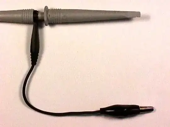
The image is from Doug Smith's webpage. You can see his plan for a much higher frequency probe here --- note the emphasis on keeping the ground connection short.
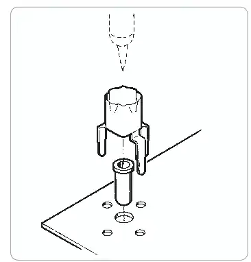
One classic way to get a good probe ground connection was with a special coaxial fixture that required a dedicated footprint on the board being tested:
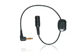
Another was the "pig-sticker" probe:
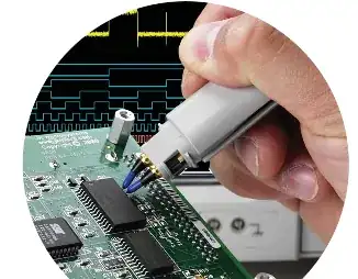
Much of the improvement in scope probe technology I've seen over the past few years has involved ever-trickier (and more expensive) accessories to provide an extremely short ground path between the probe and the circuit under test:
For your measurement you will want to connect the ground shield of the coax from as close to the cut end as possible to your probe's ground, by the shortest path possible.