2

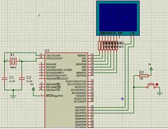
I'm trying to control a 7 segment display using PIC16F877A. I'm programming my PIC with a replica PICKIT 3.

I'm uploading my hex code using PICKIT 3 software and MPLABX IDE. I have no problem while I'm uploading my code, only when I set up my circuit.

I noticed only B1 pin is working. I did a blink LED circuit and I still get B1 pin high when I set D0 pin to high. I'm using 4 MHz crystal and 0.1 uF capacitors. I uploaded hex files from internet too, but I'm always getting high from B1.

I'm using 4MHZ Crystal with 0.1 uF capacitors. Should I change capacitors with 15 pF?

My Code:

#include <16F887.h>    
#fuses XT,NOWDT,NOPROTECT,NOBROWNOUT,NOLVP,NOPUT,NOWRT,NODEBUG,NOCPD
#use delay(clock=4m,oscillator) 
#define Dig1 PIN_D0
#define Dig2 PIN_D1
#define rfid PIN_D2
#define reset PIN_A1
#use fast_io(b)
#use fast_io(d)

static const int digit[10]= { 0b0111111, 0b0000110, 0b1011011, 0b1001111, 0b1100110,
                              0b1101101, 0b1111101, 0b0000111, 0b1111111, 0b1101111 };

void display(unsigned char value)
{
    static char tens = 0;
    char dig = (tens) ? (value / 10) : (value % 10);
    dig = digit[dig];
    output_high((tens) ? Dig2 : Dig1);
    output_b(dig);                    
    output_low((tens) ? Dig1 : Dig2);
    tens = !tens;
}

void main() 
{
   char sayi = 0;

   output_b(1);
   output_d(0b11111100);
   output_b(0b11111100); 

   set_tris_b(0x00); 
   set_tris_d(0b11111100);

   while(1)
   {
     display(sayi);

     if(input(rfid) == 0)
     {
        sayi++;    
        if(sayi == 100)
    {
      sayi = 0;
    } 
     }
     delay_ms(30);     


   }
}

My Schematic:

Schematic

PIC16F877A Datasheet: http://ww1.microchip.com/downloads/en/DeviceDoc/39582b.pdf

Real Life Circuit:
Real Life Circuit

SamGibson
  • 17,231
  • 5
  • 37
  • 58
Emre Badem
  • 23
  • 3
  • 7
    Welcome to EE.SE, Emre. You have forgotten to add a circuit schematic, your code, links to datasheets for the devices and, perhaps, a photo of your setup if it will help. It's difficult to understand how you expect us to help you without that information. All the information should be **in the question** and not in the comments. – Transistor Jul 28 '17 at 22:09
  • attach the code snippet, if possible add image of your test circuit – Raj Jul 29 '17 at 02:29
  • "I noticed only B1 pin is working. I did a blink led circuit and I i still get B1 pin high when i set D0 pin to high. I'm using 4 MHz crystal and 0.1 uF capacitors. I uploaded hex files from internet too but i m always getting high from B1." You say B1 is the only one working, but B1 is only ever high. I'm not at all clear what you mean here. I'm not at all sure what is and isn't working in general. – DiBosco Jul 31 '17 at 09:41
  • Every time I program my PIC i can't get outputs from my pins which i set as output in my code I'm only getting voltage from B1 pin although i didn't set it as a output. – Emre Badem Jul 31 '17 at 10:03
  • OK, when you set a breakpoint in your code at a line that changes the state of the GPIO, what does the debugger say is the state of TRISx and PORTx registers? You need to make sure, for a start, these are set as they should be. – DiBosco Jul 31 '17 at 11:21
  • Read the datasheet, see what it takes to get a pin into GPIO mode and code to that. All will be fine that that. – dannyf Jul 31 '17 at 11:09

1 Answers1

0

From a quick review of the hardware, I see two problems:

  1. Incorrect crystal load capacitor values:

    I'm using 4MHZ Crystal with 0.1 uF capacitors. Should I change capacitors with 15 pF?

    Excerpt from supplied schematic diagram

    Yes, you must replace those capacitors. 0.1uF is not the correct value and the crystal may not start oscillating at all when using them, or it may only work intermittently, leading to strange behaviour (like you describe).

    The required capacitor value also depends on the specific crystal, but your suggested 15pF value is likely to be close enough.

  2. Missing power decoupling capacitors

    It's not easy to fully trace the wiring in the photo, but you seem to be supplying power to the PIC via both sets of power pins (pins 11 & 12 and 32 & 31). Good, that is correct. Some people (wrongly) supply power only via one set of power pins, and then sometimes see strange, intermittent problems (especially when switching large output loads).

    However you should also add the recommended decoupling capacitors (which typically are 0.1uF) to all Vdd power pins. I don't see any power decoupling capacitors on your breadboard. Therefore add two 0.1uF capacitors - one between pins 11 & 12 and another between pins 32 & 31. Each capacitor should be close to the PIC IC itself. Again, you might see strange, intermittent problems without them.

[Note, I have not gone through your code - I am just highlighting the most visible hardware problems, which may be the cause of your symptoms.]

SamGibson
  • 17,231
  • 5
  • 37
  • 58
  • I will buy 15 pF capacitors and some PIC. I put capacitors on VDD. – Emre Badem Jul 31 '17 at 12:07
  • @EmreBadem - "I put capacitors on VDD" Good. :-) "I will buy 15 pF capacitors" Or, if you wanted, you could investigate temporarily using the external RC oscillator, instead of the crystal oscillator. Its only advantage is that you might be able to try it more quickly than waiting to buy those capacitors. Its disadvantages include worse accuracy, the program needs changing & you still need a suitable capacitor (and resistor). However, depending on what parts you have available, and how long it will take for you to get the 15pF capacitors, then perhaps you may want to consider that as a test. – SamGibson Jul 31 '17 at 13:57
  • @EmreBadem - Thanks for the update. I'm glad that the replacement crystal load capacitors (I assume 15pF) fixed the problem :-) – SamGibson Aug 02 '17 at 23:00