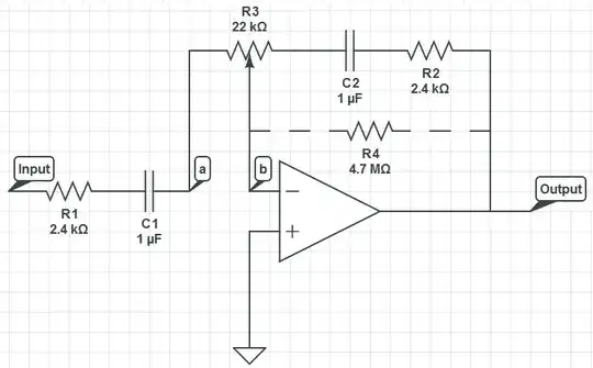
I understand that this circuit could be used as a treble control circuit with high frequency gain occuring when R3 is set so a=b (we'll call this k=0), and high frequency attenuation occuring when R3 is 22kOhms across a and b (k=1). So therefore, depending on R3's setting, this circuit is either a high pass (k=0) or low pass (k=1) filter.
When comparing this circuit to high and low pass filters, I do not understand what is happening: C2 will always have a lower impedance for high frequencies and so surely adjusting R3 will only alter positive gain for high frequencies.
I also understand that the capacitors act as an open circuit for low frequencies and so surely all low frequnencies would be attenuated.
Can you help me understand this?
Link to circuitlab.com schematic: https://www.circuitlab.com/circuit/x66cq6/basic-frequency-control-circuit/
By the way, I realise I have discussed this schematic in previous questions.
Please note: I am asking something different to any of my previous questions. This is no duplicate question.