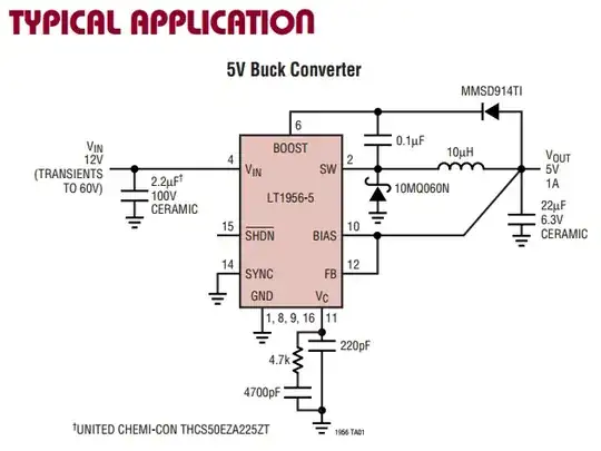
I'm running this regulator off of a ~12V car battery. I've set it up almost identically to the 'typical application' schematic and layout that the datasheet suggests to generate a 5 V output, except that I'm using a 22 μH inductor.
The problem is that when we run the starter motor, and also at undetermined points in time when the car is driving, the microprocessor on the board dies -- presumably due to some kind of glitch on the regulated 5 V.
I suspect the problem is noise, but I can't get a proper measurement of it while it is on the car. I'm going to try measure it in lab at some point.
I've got 8-9 0.1 μF bypass capacitors at the microprocessor, but apparently it isn't enough. Another problem might also be because the regulator is running in discontinuous mode most of the time. If I were to redesign it should I put some filters at the input of the regulator? Is this something that is typically necessary?
What's the best fix for this? It's too late for me to add signicant hardware to the PCB, but what would be the best thing to do if I redesigned it?
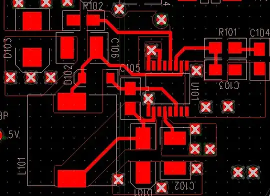
For reference, this is my layout, (C102 is the input cap, D101 is the catch diode, C106 L101 are the output filter network, R102 is a jumper to the 5V plane). The important loop (catch diode/input cap) is at the bottom.