Possible Duplicate:
Basic Frequency Control Circuit
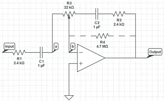
In the following schematic, why can't R4 be taken away and the feedback network pass output feedback through C2 and R2?
Possible Duplicate:
Basic Frequency Control Circuit
In the following schematic, why can't R4 be taken away and the feedback network pass output feedback through C2 and R2?
You said it yourself "DC feedback is necessary". Capacitors block DC, so a capacitor in series with the feedback path eliminates DC feedback. For the purpose of DC analysis, think of a capacitor as a open circuit.
In a perfect world with ideal op-amps, this appears to work fine since with the pot at mid-position, the gain is -1 at all frequencies* (after all, C1 blocks any dc from reaching the op-amp, so the infinite gain after point 'a' has nothing to amplify). The problem is that op-amps have input offset voltage and input bias current.
Offset voltage is a small voltage that appears to exist between the + and - inputs. Bias current is a small current which flows into the + and - inputs. The offset voltage will cause the output to change but the capacitor C2 blocks this change from feeding-back to the input and cancelling the effect. Similarly the bias current causes C2 to charge-up, causing the output voltage to increase.
Eventually, the output voltage reaches the supply rail and the op-amp saturates.