3

How does R4 prevent the output voltage drifting towards one of the supply rails to the op amp? I understand that R4 has to have a high resistance but I do not know why?

Here is the schematic which is puzzling me:

enter image description here

The link to the CircuitLab schematic:

https://www.circuitlab.com/circuit/x66cq6/basic-frequency-control-circuit/

user1083734
  • 365
  • 1
  • 4
  • 11
  • 5
    That looks like a Circuit Lab schematic! It would be great if you could post a link to the schematic so that answerers could edit, highlight, and reconfigure it if necessary. – Kevin Vermeer May 14 '12 at 18:13
  • I love Circuit Lab, but for some reason I cannot save anything I have drawn on it. Otherwise I would, any suggestions on how to save and I would gladly post a link – user1083734 May 15 '12 at 08:30
  • I've since found out that the save functions aren't supported by the Chrome I'm using, I will post a link once I have redrawn using Firfox – user1083734 May 15 '12 at 08:59
  • https://www.circuitlab.com/circuit/x66cq6/basic-frequency-control-circuit/ I have changed the capacitors to 2nF – user1083734 May 15 '12 at 09:14
  • @user1083734 shame on CircuitLab not supporting Chrome! – abdullah kahraman May 15 '12 at 11:00
  • @abdullahkahraman It may just be a bug. They do include instructions to enable javascript on Chrome so maybe it is a fault with my installation. – user1083734 May 15 '12 at 11:35
  • CircuitLab does support Chrome, and works fine without any special 'javascript enable' steps. Is [this](https://www.circuitlab.com/forums/support/topic/ubzhvq5w/circuit-lab-wont-save-anything/) your Forum thread? You need to be logged in so that the editor knows whose account the circuit should be registered to. – Kevin Vermeer May 15 '12 at 14:04
  • Yes, it is my thread. I am logged in when I try to save, I click "Save As" and no window appears like it does when I use CL on firefox – user1083734 May 15 '12 at 14:11
  • I understand that this circuit could be used as a treble control circuit with treble gain occuring when R3 is set so a=b, and treble attenuation occuring when R3 is 22kOhms across a and b. When comparing this circuit to high and low pass filters, I do not understand what is happening: C2 will always have a lower impedance for high frequencies and so surely adjusting R3 will only alter positive gain for high frequencies. Can you help me understand this, or should I post a new question? – user1083734 May 16 '12 at 08:56

4 Answers4

6

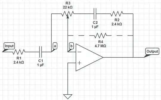
Without R4, you do not have any DC feedback because the only negative feedback path is through a capacitor. Without DC feedback, you don't have a stable DC operating point.

If R4 has a low resistance (let's say, for the sake of argument, zero). In this case, all the negative feedback goes through R4 (path of least resistance) and the R2/C2 branch of the circuit does nothing.

Intuitively, though, the 4.7 Megohm choice for this resistor seems quite high. For this to work well, you need an op-amp with a very high input impedance (e.g. JFET input).

The idea in this circuit is that R4 conveys the DC output voltage from the output of the op-amp to the non-inverting input, and the impedance at that input is so high that it draws nearly zero current, allowing such a high valued resistor to be used.

Even without doing any calculations, I think a much lower resistance for R4 would still work there.

Kaz
  • 19,838
  • 1
  • 39
  • 82
  • So, would you say a 1MOhm resistor would be more appropriate? I was told that if it were too low, the circuit would not work correctly. – user1083734 May 15 '12 at 08:35
  • 1
    Pick a frequency, like 100Hz and compute the capacitive reactances of C1 and C2 at that frequency. (The reactances at 1000Hz and 10,000Hz are then just 10x and 100x smaller.) From the reactances you can determine the impedances of various branches of the circuit at those frequencies, giving you a sense of what the signal is facing, and how significant is a given value of R4 in that picture. – Kaz May 15 '12 at 21:08
  • I understand that this circuit could be used as a treble control circuit with treble gain occuring when R3 is set so a=b, and treble attenuation occuring when R3 is 22kOhms across a and b. When comparing this circuit to high and low pass filters, I do not understand what is happening: C2 will always have a lower impedance for high frequencies and so surely adjusting R3 will only alter positive gain for high frequencies. Can you help me understand this, or should I post a new question? – user1083734 May 16 '12 at 08:52
  • @user1083734 It's not clear what you mean, but your assessment is right. The circuit's control does not sweep over the frequency range. It is just gain for high frequencies, a treble control. – Kaz May 16 '12 at 15:11
6

With R4 removed, there is no DC feedback path from the op-amp output to the input. So if the b node drifts away from ground, there's nothing the op-amp can do to drive it back towards ground (which it will try to do to keep the two inputs equal). If b drifts high, the output will tend to rail negative, and if b drifts low the output will tend to rail positive, according to the open-loop gain of the op-amp.

With R4 in place, you have a DC feedback path. If b drifts high, the op-amp output can go a little bit low and pull it back to ground. If b drifts low, the op-amp output can go a little bit high and pull it back to ground.

Put in more jargonistic terms, with R4 removed the DC circuit is an open-loop amplifier. With R4 in place, the DC circuit is a voltage follower.

The Photon
  • 126,425
  • 3
  • 159
  • 304
  • I understand that this circuit could be used as a treble control circuit with treble gain occuring when R3 is set so a=b, and treble attenuation occuring when R3 is 22kOhms across a and b. When comparing this circuit to high and low pass filters, I do not understand what is happening: C2 will always have a lower impedance for high frequencies and so surely adjusting R3 will only alter positive gain for high frequencies. Can you help me understand this, or should I post a new question? – user1083734 May 16 '12 at 08:52
  • It would make more sense to make it a new question --- partly because there's other people here who know much more about audio than I do. – The Photon May 16 '12 at 16:19
3

I agree with what the others have said about what R4 does in the circuit. However, I would put it accross C2 only, not where it is now. That way the high pass filter rolloff frequency it causes won't change with other parameters in the system. For example, if you wanted the high pass rolloff to be 20 Hz, then a resistor just accross C2 would be 8.0 kΩ, so 10-15 kΩ would be good if this is audio.

Having the high pass filter rolloff too low causes long startup transients and glitches. You want to block frequencies below what you care about, but you also don't want the time constant to get to steady state operation to be too long. 1 µF and 4.7 MΩ is a time constant of 4.7 seconds, and it could take multiple time constants before the system settles to steady state operation. That's definitely unacceptable if this is a ordinary audio device.

Olin Lathrop
  • 310,974
  • 36
  • 428
  • 915
  • Olin, I think you mean R4 across just C2, rather than C2 + R2, right? About the RC time constant, why would we care about C2 versus R4, when C2 is not charging through R4? Thanks. – Kaz May 14 '12 at 21:49
  • @Kaz: Yes, sorry, that somehow got lost in scrolling back and forth between typing the answer and the schematic. Fixed. – Olin Lathrop May 14 '12 at 22:39
  • I understand that this circuit could be used as a treble control circuit with treble gain occuring when R3 is set so a=b, and treble attenuation occuring when R3 is 22kOhms across a and b. When comparing this circuit to high and low pass filters, I do not understand what is happening: C2 will always have a lower impedance for high frequencies and so surely adjusting R3 will only alter positive gain for high frequencies. Can you help me understand this, or should I post a new question? – user1083734 May 16 '12 at 08:53
0

Your Op Amp has > 100dB of DC gain and your design will integrate to the supply rails every time, because you have almost designed an "Integrator"

added An interesting idea has come out of your oversight. If capacitors C1 & C2 come from the same batch and are matched, they may have the same leakage and thus your DC output gain will be unity but with a really large RC time constant depending on the leakage values. If one wanted to perfect this oblique application, consider Panasonic Polyurethane plastic caps. Now any change in leakage of C2 will result in a gain change, likely in orders of magnitude, so it has in fact become an extremely sensitive uA meter or leakage meter, which has all sorts of applications such as smoke detectors. Using C1 itself as an instrument probe, your tester with,C2 as your matched benchmark for leakage, you now have a very sensitive Leakage controlled DC gain for measuring changes in leakage. You would have to periodically dump the charge on C2 to null the integrator. You might consider a leakage detector useful for measuring soil moisture or fluid contamination measurements. Of course there other ways to instrument this, but this method wil match values on C1,C2 has an interesting unity gain condition for DC. an Offset adjustment pot would be useful across the +/- inputs to Vdd. YOu could consider this as an alternative for those expensive medical devices that measures the leakage in plasma using an OmegaMeter or leakage in distilled water from contamination, or looking at the leakage of fresh solvents after the last rinse to verify contamination free of aerospace exposed material in a clean room. Either way, you have nullified the huge DC gain now by matching component values with extreme low loss Polyurethane caps or better yet Teflon Caps but made it sensitive to leakage changes if you expose one part C1 to the test condition. Using it as a GO/NoGo tester one can use a small DC voltage, say 1.5V to force a leakage no go test relative to a fixed resistance across C2 such as 100MΩ or 1000MΩ. If the output saturates in the opposite direction ( biased by external battery source ) One can say the new leakage across C2 probe meets or fails the defined reference Rf test criteria. a.k.a Wheatstone bridge with gain of 10 billion or more comparator to reference resitor Rf. You would also want to null common mode noise so the Op Amp's output could be used as a shield or twisted pair.

Of course the prefered design with bypass feedback resistor could also work across C2, it just becomes a HPF pole that is affected also by gain control Pot, not recommended.

Tony Stewart EE75
  • 1
  • 3
  • 54
  • 182