You don't seem to understand the operation of a nixie tube at all.
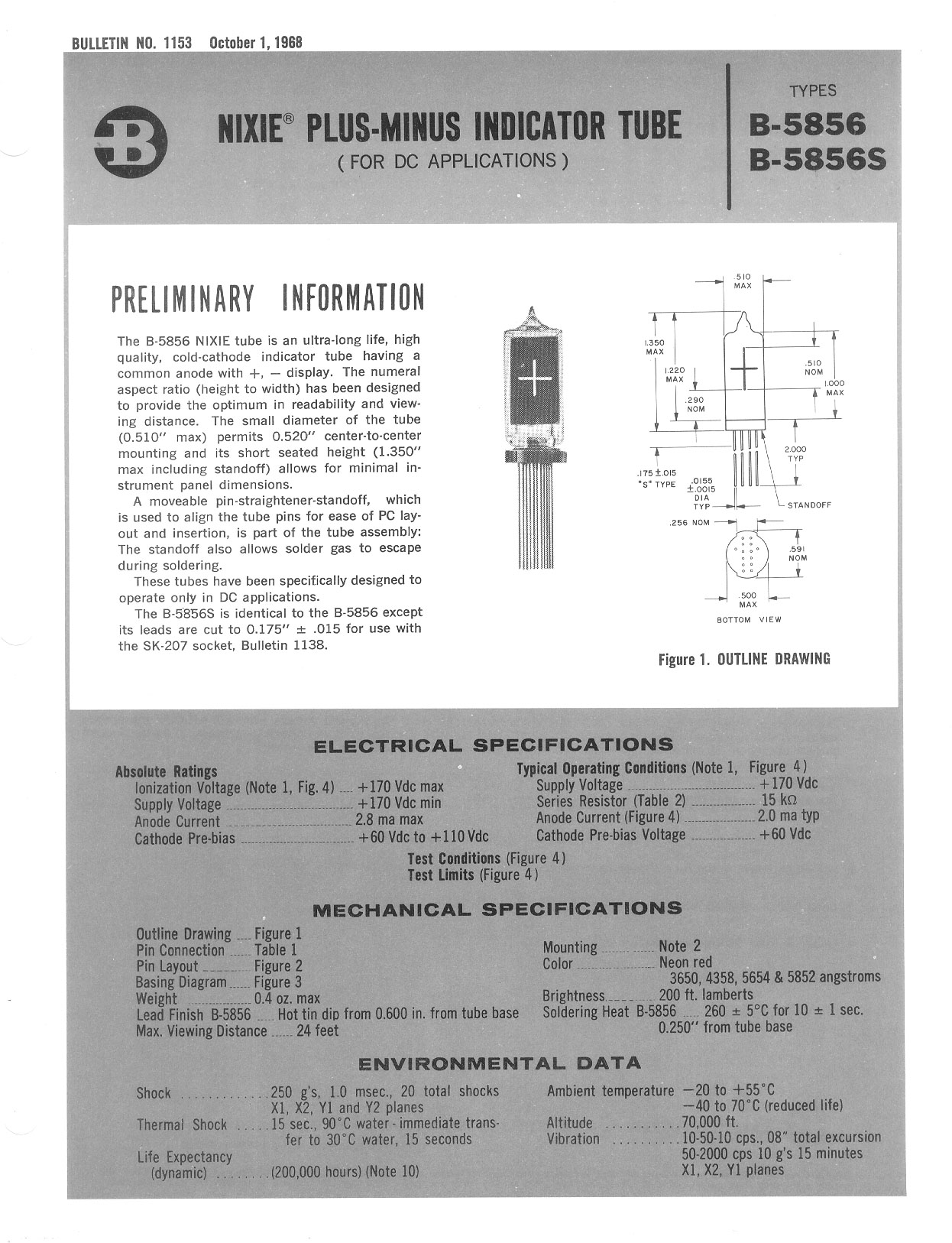
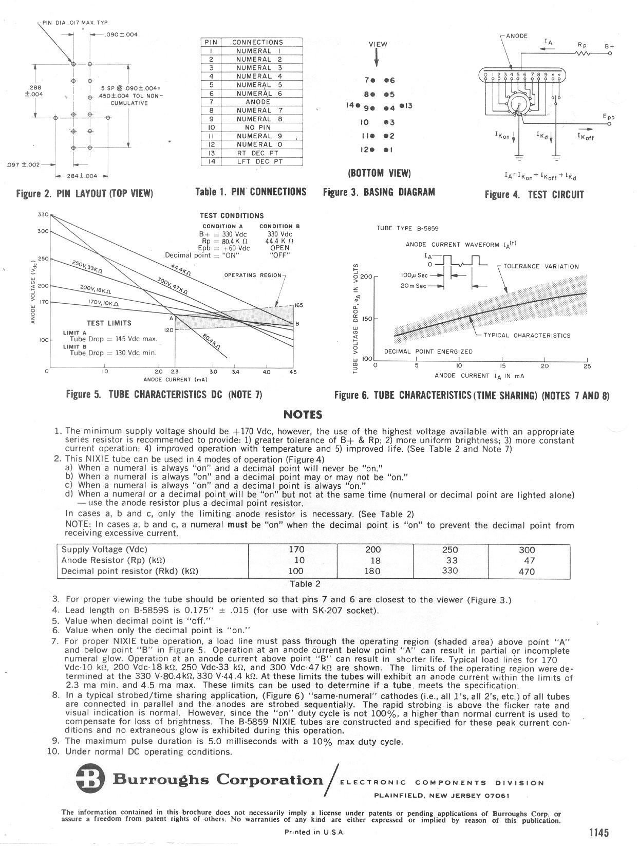
You need the datasheet for your Nixie, since you don't specify it, here's a typical one of the old stock available on Ebay ...Burroughs B-5859 page 1 and page 2.
The critical section from page 2 is shown here:

I've added lines for the current (3.4 mA) and the tube segment voltage when alight. You can see from the voltage on the Y axis the supplied voltage is always well above the tube sustaining voltage.
The way each number in the tube operates is that the voltage rises above what is called the strike voltage, and once conducting this voltage falls to the sustaining voltage.
In the schematic you provided, notice that the power supply voltage is in fact 180 V DC.
With the tube shown above if you had a 170 V DC power supply and 130 V sustaining voltage you would have an anode resistor of:
(170 - 130) / 0.0034 --> 11.7k Ohm
If the sustaining voltage was 145 V, then the anode resister would be:
(170 -145) / 0.0034 --> 7.3k Ohms
So in each case only a small portion of the power supply voltage is across the anode resistor, the majority of the voltage is the sustaining voltage across the tube element that is on.
The sustaining voltage for the Nixie tube varies from tube to tube and also varies depending on temperature and exposure to light. (A tube is harder to start in the dark)
Additional info
Since you've now pointed out the tube you are using (IN-8-2), here's some more points to think about.
The current rating to get all the digits to appear constant brightness means that for each digit you need separate current control. If you don't do this then digits such as "1" appear very bright while an "8" appears much dimmer.
It's also a challenge when using digits and the decimal dot, since if this tube is not multiplexed, you have to design to ensure both the digit and dot can run together (you can do this by having a negative supply for the dot).
Since you typically only have a single anode resistor this means that you need to add separate resisters to the cathode pins to control the current individually.
Let's try an example, though I don't know the absolute currents required for each digit, so will propose guess values using the datasheet data.
From the datasheet:
- We know the worst case firing voltage is 170 V, so lets set the PS at 180 V DC. The datasheet tells us not to go above 200 V DC.
- We know the lowest sustaining voltage is 100 V DC.
- The maximum current we'll set at 3.5 mA for the "8" digit"
- Lets assume the "1" digit will half of the "8", so about 1.75 mA.
Let's assume also that the anode resistor is all that's needed for the "8" digit, we won't use a cathode resistor.
The anode resistor is then:
(180 - 100) / 0.0035 --> 23k Ohms with no cathode resistance required.
When the "8" cathode is pulled to ground, the voltage will be above the strike voltage. Once the digit is on the anode will be at 100 V DC (worst case), so there will be 80 V across the anode resistor (0.28 W, so I'd fit a 1/2 W resistor). If the sustaining voltage is higher for the tubes, say 130 V then you may have to recalculate the anode resistor, since this would drop the digit current.
For the "1" digit the resistance needed is:
(180 - 100) / 0.00175 --> 45k Ohms. Since we have 23k already in the anode the cathode resistor needs to be (45 - 23) --> 22k Ohms.
When the "1" low side resistor is pulled to ground you'll have about 40 V across the cathode resistor and 40 V across the anode resistor.
Having built a bunch of clocks (though they were all multiplexed) based on Nixies in my misspent youth, my opinion is that it's best to use a constant current low side driver with one anode resistor setting the maximum safe current. It's then easy to use a 4 bit D/A to set the current values for each digit/dot as you multiplex through them, especially it the clock is MCU based.


