28

So I want to make a Lazy Susan that is rotating constantly in one direction. I also want to have some other things on top such as neon signs, moving things, and etc. Problem is I want this to all run off of one DC source. Problem is I cannot figure out how I wire it so that things don't get tangled since the entire thing is constantly in motion.

Sie
  • 437
  • 2
  • 6
  • 9
  • 27
    Google for "Slip ring" – Eugene Sh. Jul 18 '17 at 20:44
  • On eBay, they'll all come up when searching for: slip ring capsule. Also, Adafruit has one for twenty bucks – wbeaty Jul 18 '17 at 23:47
  • 1
    Generally speaking, you have the choice between some sort of a slip ring/commutator, a rotary transformer, or photovoltaic cells. – Hot Licks Jul 19 '17 at 03:16
  • 2
    @HotLicks a small PV cell and a very big laser? That would look good too. – Chris H Jul 19 '17 at 08:20
  • 3
    Maybe get a few worn out or cheap electric toothbrushes, and commandeer the wireless charging parts? – rackandboneman Jul 19 '17 at 08:58
  • It is also possible to have a generator on the platform with a shaft locked to the base and have the base driven by a over designed motor that can drive the generator and the platform. You will need gearing of some sort. Search for "Propeller Clock" – KalleMP Jul 19 '17 at 21:03
  • @ChrisH 35 years ago a company in South Africa was developing mining detonators that were ignited by laser pulses down optical fibres so the amount of light can be rather high. The idea was to prevent induced voltages from lightning etc from causing premature detonation on surface work. – KalleMP Jul 19 '17 at 21:06
  • 1
    @KalleMP I've heard of various devices powered by light down fibres in explosive atmospheres, but never a detonator until now. – Chris H Jul 19 '17 at 21:24
  • 2
    You could also ignore electronics on the rotating part. You can shine a bright light (laser maybe) across the air gap into a fiber optic in the center of the lazy susan and create "neon" effects if the fiber leaks a little. The mechanical "moving things" can be powered by the mechanical rotation of the lazy susan with gears. Not everything needs to be electronic. – Mark Lakata Jul 19 '17 at 22:56
  • 2
    Seen one of [these](http://www.viking-direct.co.uk/catalog/catalogSku.do?id=6451956)? – Boris the Spider Jul 20 '17 at 12:01
  • 1
    @BoristheSpider well spotted we have used similar for years and never gave the rotational feature any thought, 3 contacts rated for many amps, and self aligning if placed in a somewhat flexible mount. I would go with this if I had to make just one or two. Buy a couple of used kettles via local classified or fleamarket and hack the guts out. – KalleMP Jul 20 '17 at 17:38
  • Standard car alternators have two sliprings good for many amps to drive the rotor winding. Stripping them and making them work will be a lot of effort but gutting a unit from the scrap yard might give you ideas. These are VERY durable units. Wow, lots of choices - https://www.google.fi/search?q=car+alternator+slipring&tbm=isch – KalleMP Jul 20 '17 at 17:40
  • Continuous or start stop rotatoion? Variab;le or constant sped rotation? Mono directional or bidirectional? What rotation speed range? What power transfer wanted - peak, mean? – Russell McMahon Jul 26 '17 at 04:51

10 Answers10

49

You are looking for a slip ring. This is a device designed to do exactly what you describe - transmit power and/or signals to a rotating object. Generally, they work by having a rotating circular contact on one side and a spring-loaded pin which pushes against it on the other.

They are not super reliable long term or in harsh conditions, but should be fine for your project. More expensive ones are generally better and last longer. The other alternative is inductive power transfer/signalling, but this will be harder to get right first time, so might not be ideal for a hobby project.

Jack B
  • 12,167
  • 1
  • 27
  • 46
  • They're used on CCTV cameras and stand up pretty well to long-term outdoor conditions, years of constant movement etc. with power & video (analogue & IP) going through them. I can't vouch for the cheap eBay ones but good ones do last. I'd avoid loading them too near their maximum rating, but you can get one with more contacts than you need & double-up for reliability. – John U Jul 20 '17 at 10:23
  • I've worked on a project that has a slip ring transmitting ~30A at 12VDC along with communications signals to a board that is rotating at 3000RPM. The reliability wasn't *great* but it was acceptable. For something that only rotates slowly, I'd imagine you'd have a life time of 5 years or more. – Jules Jul 20 '17 at 15:44
  • Slip rings can be reliable. You can even get slip rings for ethernet. They just become ridiculously expensive. Even more on high speed. – Jeroen3 Jul 21 '17 at 05:46
48

An alternative to slip rings is the rotary transformer. This consists of two cup-shaped cores that face each other, with the windings inside the cups. If you drive the primary at a high frequency (we used 25 kHz), the cups can be ferrite and the whole thing can be quite compact (we did about 100W in a unit that was about 1" thick overall and about 3" in diameter).

cross-section

Dave Tweed
  • 168,369
  • 17
  • 228
  • 393
  • 14
    In case anyone wonders about reliability and data transfer quality and all that stuff for these: your average VHS rotating head worked that way. – PlasmaHH Jul 19 '17 at 08:26
  • One other mechanical issue that complicates this a bit: how small must you make the airgap in order to make this relatively efficient? – Jason R Jul 19 '17 at 11:47
  • 1
    @JasonR: The smaller, the better, of course. We didn't have a lot of precision in our prototype assembly, and were getting good results with a gap on the order of 1 mm. That's one reason we used a relatively flat core design -- it maximizes the surface area of the ferrite facing the gap. – Dave Tweed Jul 19 '17 at 12:01
  • I might have to consider this because I was looking at slip rings on eBay and they will work for the Lazy Susan but I also need slip rings (or something else that will work like it) for high RPM uses. High RPM being in excess of 3,000RPM. – Sie Jul 19 '17 at 18:23
  • 1
    Yet another possibility would be to have a moving coil within a fixed magnetic field--otherwise known as a generator. – supercat Jul 20 '17 at 15:15
  • @Sie - As mentioned in a comment above, I've worked with slip rings on a project that rotated at 3,000RPM and it did work, although the life time of the rings was fairly short. – Jules Jul 20 '17 at 15:47
  • 1
    @supercat: Not really effective in a "lazy susan" application, where the rotation can be expected to be slow and/or intermittent. – Dave Tweed Jul 20 '17 at 17:01
  • @DaveTweed: According to OP, the device was expected to be rotating constantly. Gearing may be necessary to make a generator useful, but that wouldn't necessarily be a problem. – supercat Jul 20 '17 at 20:10
  • @supercat power transfer would be proportional to rotation speed, which probably wouldn't be high enough to make this useful. Then there's other considerations like extra load on the motor from the weight and friction of the drive mechanism and gearing for the generator, and the load of the generator itself. – MBraedley Jul 25 '17 at 19:01
  • @MBraedley: Yeah, I'm not sure what kind of "gearing" supercat has in mind. Obviously, you can't spin the coil, because then you'd be back into a slip rings/brushes situation, so he must be thinking about spinning the magnet(?). Or else using an arrangement with a really high pole count, such as a stepper motor. A 200 steps/rev. motor spinning at 4 seconds/rev. would give you a 50 Hz waveform at the coils, but I suspect that the overall efficiency would be really horrible. – Dave Tweed Jul 25 '17 at 19:19
  • @Dave Tweet: nitpicking here, check the winding direction of your coils. It should be same for both upper and lower coil, the same as for a long coil. – Janka Jul 26 '17 at 12:24
  • @Janka: You're picking a non-existent nit! The relative polarity of the coils doesn't matter one bit. If you're referring to the markings in the image, take it up with Wikipedia -- it comes directly from the linked article. But I think it's correct, assuming that the markings refer to the direction of the current, not the polarity of the voltage. – Dave Tweed Jul 26 '17 at 13:29
  • @Dave Tweed: e.g. the left flux encircles the wires in clockwise direction. This cannot be connected with current running **both** into the plane and out of the plane. It's simply not possible. If you have two wires adjacent to each other running the same current in opposite directions, the encompassing flux is null. – Janka Jul 26 '17 at 16:48
  • @Janka: Yes, exactly! The flux from the secondary current *cancels* the flux produced by the primary current -- that's how a transformer works. The flux shown in the diagram is the leftover "magnetizing" flux, which is really due to primary current only. – Dave Tweed Jul 26 '17 at 18:33
  • @Dave Tweed: You are right! But the image is still misleading. I talk to the author. – Janka Jul 26 '17 at 19:18
9

How about using two rings of ball bearings and use each ring as the contact. No need to add pins and contacts...

Just to add, after taking note of the comments, that I was thinking of a low voltage supply here 5v or 12v just for leds or somesuch - I was not intending to suggest a 110VAC or 230VAC solution.

Solar Mike
  • 6,319
  • 1
  • 12
  • 28
  • 23
    The arcing on the bearings should add that extra bit of excitement that the neon signs on top are lacking! +1 for concept. – Transistor Jul 18 '17 at 21:13
  • True - perhaps the neons could be replaced by leds to reduce voltage and power - must admit i had missed the implication of neon... – Solar Mike Jul 18 '17 at 21:15
  • 29
    Passing electricity through ball bearings pits the balls resulting in premature failure of the bearings – Tinkerer Jul 18 '17 at 22:02
  • 5
    ... or early onset of arcing. Whee! – Transistor Jul 18 '17 at 22:28
  • 2
    This page by SKF (I gather they're supposed to know a thing or two about bearings) lists some nice examples of why this would be an... _interesting_ idea: http://www.skf.com/cn/en/products/bearings-units-housings/roller-bearings/principles/troubleshooting/bearing-failures-and-their-causes/bearing-damage/passage-of-electric-current/index.html – Mels Jul 19 '17 at 14:46
  • @Mels Do you really need skf bearings for a lazy susie? – Solar Mike Jul 19 '17 at 14:51
  • @Mels also the page you refer to is talking about electric arc welding so approximately 80v and 40 to 160amps - not what I was suggesting with 5v or 12v and a few leds etc – Solar Mike Jul 19 '17 at 14:57
  • @SolarMike no, they say that "At the contact surfaces the process is similar to electric arc welding". They go on saying "Both alternating and direct currents cause damage to bearings. Even low amperage currents are dangerous." - although they don't quantify what they see as a "low amperage current", the message I take from that is that a good design shouldn't rely on current passing through a ball bearing. – Mels Jul 19 '17 at 15:02
  • @Mels good design true, but we are talking about a lazy susie.... And having seen people welding on lathes - it's not something I would suggest. – Solar Mike Jul 19 '17 at 15:06
  • Nice idea in spite of the suboptimal use of bearings. I expect that multiple ball races will cost more than a slip ring assembly. If you have large ball count thrust bearings there may be a large number of bearings in electrical contact and the problem may be less severe than sending welding currents through a car wheel bearing. – KalleMP Jul 19 '17 at 20:59
  • 1
    @KalleMP suboptimal :) I agree up to a point - the lazy susie needs to have some rotational support and an inner and outer ball race may also help with stability - the one I have does wobble a bit as the bearing support is close to the centre. – Solar Mike Jul 19 '17 at 21:02
  • 4
    As a practical matter, it will be difficult to get multiple bearings aligned precisely enough that they are carrying equal loads (i.e., equal contact pressure on both sets of balls) at all times. It's very likely that at least some of the time, one bearing or the other will be handling most of the load, with very intermittent contact on the other. – Dave Tweed Jul 19 '17 at 23:39
  • @DaveTweed Good point, I might elect to go with a taper roller (or just angled roller) bearing for centering and a flat needle bearing for thrust. If the platform deforms enough to place both bearing races under some preload then there is a small chance of sending a few watts through with some measure of success. – KalleMP Jul 20 '17 at 17:25
  • 1
    @Mels with high enough current you can make the ballbearings supply the motive force :-) This is the limit that one can take the current supply though but I have seen such motors operating at a display at the Hannover Fair for a week (perhaps at multiple shows) without incident. https://www.youtube.com/watch?v=DjKhggNJGls – KalleMP Jul 20 '17 at 17:30
  • While the skepticism of the commentors is well-warranted, you may be able to get by with low currents, and a generous amount of electrically conductive lubricant in your bearings. The lubricants are not super-great conductors, more often than not used to mitigate static buildup, but it might buy you enough conductivity to prevent ruining the bearings. – whatsisname Jul 20 '17 at 17:32
3

The other option that you may not have considered is to put all of your power consuming items, including the motor, and the batteries or other power source onto the lazy Susan. No electrical connectors to the outside world required then.

Steve Barnes
  • 191
  • 3
  • 8
  • 2
    This did occur to me as well, it depends on how long the system must operate unatended. Use Bluetooth lowpower to communicate with the stationary inertial space with minimal power waste. – KalleMP Jul 20 '17 at 17:32
  • 1
    @KalleMP or if the rotational rate is reasonably low simple IR comms, if higher omnidirectional IR transducers. – Steve Barnes Jul 21 '17 at 03:44
3

It has occurred to me that if you are driving the lazy Susan at a reasonable rate you are also in a situation where you can generate power on it.

If either on the central spindle or round the edges you could mount fixed magnets you could use appropriately placed coils to generate power on the moving platform.

If you were looking for really low tech you could even use an old push bike dynamo on the rotating platform running against a stationary surround of some sort.

Steve Barnes
  • 191
  • 3
  • 8
1

Slot cars get their power from braid running on conductive tracks. You might be able to glue flattened coax cable shield (braid) in two concentric circles on your base board and then use braid "brushes" to pick up the voltage.
Or use one circle and brush and pick up the other side of the voltage via the central pivot.
Or use the central pivot as one contact, run the braid around the outside of the platter and use a horizontal brush.
Or think about the good old Dodgem cars where the floor was one contact and the wire mesh ceiling the other. Cover the whole of the base board with heavy duty domestic aluminium foil (leave a hole in the centre). Attach a brush to anywhere on the platter as one contact and use the central pivot as the other contact.

raysputin
  • 76
  • 1
1

I looked into this recently building a zoetrope with LCDs and a microcontroller on the spinning top. I ended up making a DIY slip ring assembly from copper sheet and some carbon brushes designed for drill motors. It worked out surprisingly well (still good after 100,000 or so revolutions).

Before I went down that road though, I investigated wireless power transfer and that looked really hopeful using a cheap tx/rx pair of modules like this: wireless power modules

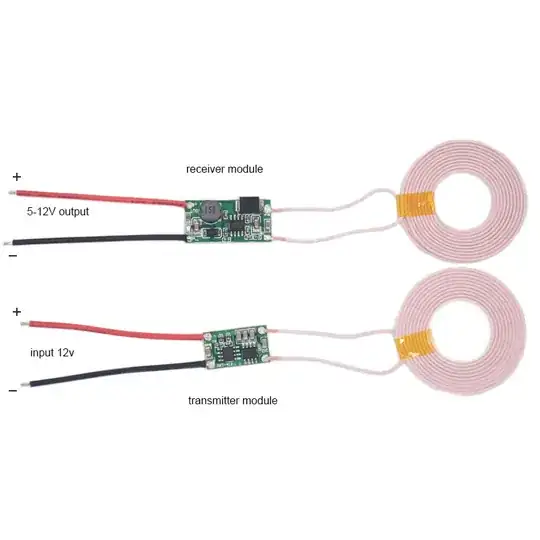
Passing the drive shaft through the transmitter and attaching the receiver to the underside of the lazy Susan worked pretty well if you can keep them close together. It didn't provide enough current for my application (I needed about an amp and these give about 500mA comfortably).

For my application I also needed to pass very low-rate uni-directional data from the base to the top, rather than add to my slip ring assy, I used IR LEDs and receivers, that worked really well.

Al Bennett
  • 799
  • 4
  • 7
0

Nicola Tesla said you could have a toothed ferromagnetic wheel on the rotor and stator each with windings. A combination transformer and synchronous clock motor. That avoids the legal expenses that you will have with liquid mercury, ozone poisoning, or electrocution.

richard1941
  • 632
  • 3
  • 7
  • 1
    (1) This answer is rather vague and unlikely to be of much use to the OP. (2) Can you give a reference for what Tesla said? How many RPM do you think a lazy susan would require to generate enough power to light the OP's neon signs? (3) Your sentence "*A combination transformer and synchronous clock motor.*" is missing a verb and a subject. What did you intend to communicate? (4) What is a combination transformer? (5) How would a synchronous clock motor help? – Transistor Jul 26 '17 at 11:43
  • My reference to Tesla was just a reminder that he is the progenitor of most of our AC motor, generator, and transformer technology. The speed of the rotor is inversely proportional to the number of teeth that engage the flux. Now imagine a small winding around each rotor tooth.... that would have an induced voltage because of the changing flux. Of course, if you do the power budget, the result of this would be equivalent to increased drag and a greater phase lag in the input current. Hope this comment helps. I will have to dig for my electric machines text if you need a reference. – richard1941 Jul 27 '17 at 12:47
  • It would have to be rotating too fast so for this application, but might work for others that find this thread via google. – C.M. Apr 13 '19 at 21:21
0

Tweed's rotary transformer is probably the best solution when it is possible to wrap a coil around the axis and have a ferromagnetic core for the axel. But you could have a set of several smaller coils around the edge with similar coils coupling to them on the rotating platform. The power from each would be intermittent, but if they were properly spaced, you might meet your needs. Do expect nasty 60 Hz vibrations as the coils pass each other... unless you drive them at 100 kHz and use lightweight ferrite cores... If you want to go to high frequency, you might do some kind of capacitive coupling, as suggested by that great Scottish poet, R.F.Burns.

richard1941
  • 632
  • 3
  • 7
-1

Use two rings, as with the ball bearings, but eliminate all wear and arcing with rings of liquid mercury or other conductive fluid. Don't drink it! Of course air is a conductive fluid at high voltage, and the display would earn respect of your guests and discourage nibbling of the marzipan and aboutargo on the rotating platform.

richard1941
  • 632
  • 3
  • 7