2

I have a simple arduino driven charger for solar energy to pass into 12V lead-acid battery. However, to use the stored energy I need an analog circuit to cut off discharge at 11.5V. I think a voltage divider ( or 10V zener ) to a N-MOSFET (IRF630), or via a small signal N-MOSFET (2N7000) to a P-MOSFET (IRF9630), plus some extra bits, may be sufficient to switch a relay. I would prefer ditching the relay but then I'd need to heavily heatsink the MOSFET.

My main concern with the relay method is that the relay itself pulls about 0.33W when normal-closed (to clarify, this is also when I discharge the battery), which is a waste. Is there a best practice for cutting off 12V batteries? I have found many on google, of course, but most are 'instructable' type methods, others are rather bulky.

user2497
  • 312
  • 4
  • 13

1 Answers1

6

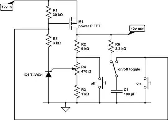
M1/IC1 form the latching 'thyristor type' power switch. It draws no power when off, and little when on.

schematic

simulate this circuit – Schematic created using CircuitLab

The TLV431 (not the right symbol, this was close) is designed as a 3 terminal shunt regulator, that maintains the sense voltage at 1.24v. You could think of it as a high gain NPN transistor, with a 1.24v base threshhold voltage.

Consider what happens at the switch point. The sense voltage is around 1.24v, the supply current is passing through 200uA so there's 6v on its supply. This is within its normal operating conditions. Any tiny change in output voltage in either direction will result in switching off, or staying well latched.

I've tested the performance of the TLV431 open loop, and it's well behaved. The cathode stays above 1v, even when ref is well above 1.24v, and it comes out of 'saturation' with no hysteresis. With a cathode resistor of 33k, and 12v supply, it goes from full on to full off in about 4mV of ref terminal movement.

Note that the TLV431 is an unusual device in that the same part number from different suppliers has different specifications. The Texas device only works to 6v, so cannot be used here. The On Semi, Diodes Inc and Zetex devices are specified to 16v, so should be OK. There may be other manufacturers I have not named.

I've shown the components I use to toggle the circuit on and off. Note that for toggling off, the load voltage has to collapse far enough while C1 is holding the FET off. It has only the time constant C1.R5 to do this. If the load has a large reservoir capacitor and a low load, the time constant may need to be increased further.


This is an updated circuit several years later, and contains a number of improvements.

  • It won't switch on if the battery is below threshold
  • It will support much higher voltages, limited by Q1 and M1
  • It is integrated with the power-on LED, to save current
  • It has a fast load discharge option when turning off

schematic

simulate this circuit

In order to inhibit switch on if the battery is low, the ON switch connects the input voltage to the voltage measuring divider chain via D3, and conveniently the ON LED to show that something is happening. If the voltage is high enough, IC1 turns on, using Q1 as a cascode to get the on signal current up to M1, which turns on, connecting the load, and maintaining the input voltage via D2. The ON button can now be released. D1 limits the gate voltage for high voltage battery inputs. D2 prevents the ON switch from powering the load directly.

TLV431 only goes to 6 V or 16 V (see above, though I think TI have now released a higher voltage one), TL431 goes to 36 V. If 36 V is enough, then if using TL431 Q1 can be omitted and R8 increased, however it requires a higher reference input current drive than TLV431.

I'm using a blue or white ON LED for double duty as a regulator, the slope resistance is an order of magnitude better than a Zener at this voltage. Choose R7 for a few mA if it's needed as an ON indicator, or for 100 uA if it's not.

When coming to turn the circuit off, large capacitors in the load may hold the load voltage above the battery minimum threshold for long enough to be tedious, pressing the off button and waiting for it to stop. R11 allows you to actively load the output when turning off, choose a smaller value of R11 to discharge faster. The maximum current you can draw from the load is limited by R11 pulse load handling, D2 and the off switch current handling.

Use of D2 and D3 reduces the threshold accuracy slightly, but I don't think significantly. R9 and R10 are shown for approximately 11 V threshold, about the minimum for nominally 12 V lead acid batteries.

Neil_UK
  • 158,152
  • 3
  • 173
  • 387
  • What's the comparator? Can you recommend a specific part? – user2497 Jul 19 '17 at 07:31
  • 1
    No, you can use any part you like, that will fit with your rails and budget. You mentioned 339 in a comment above. That's a quad, the 393 is its dual equivalent, which will use less power, but with those resistor values, the odd mA probably won't fuss you. You could increase the values of the resistors, those are only suggestions, though keep the ratios (mostly). Now normally, we'd advise against using an op-amp in a comparator position. Here, why not? As soon as it begins to chatter at the threshhold, the supply will turn off, job done! Even the rightly hated 741 would work here! – Neil_UK Jul 19 '17 at 07:44
  • 1
    @user2497 I've added a bit to my answer. Note the caveats about the supplier of the part, and the fact I haven't tested it yet. – Neil_UK Jul 19 '17 at 11:00
  • Excellent - so anything at or below 1.23V will not trip the circuit closed? I like the new circuit design. – user2497 Jul 19 '17 at 11:58
  • That's the idea. Do try it and let me know whether it works. – Neil_UK Jul 19 '17 at 12:48
  • 2
    @user2497 I've had a further thought about the second circuit. I've still not built one (you're getting real-time thinking here), but I've worked out what the minimum addition should be such that it regulates properly all the time, so I'm much happier that it should work as expected. In case you wonder why I'm spending this effort, I need exactly this circuit for my own purposes, so it's nice to use your question to kick me into designing it! – Neil_UK Jul 19 '17 at 15:39
  • You are pioneerin'. It is very useful to have when running off 12V batteries. Keep me posted – user2497 Jul 19 '17 at 15:46
  • Is IRF9530 a typo? I have found the comparator in an SMD package, though TO-92 or TO-220 would be preferred. – user2497 Jul 19 '17 at 23:50
  • In your second schematic, shoulf the TLV431 be wired before or after R4? – user2497 Jul 20 '17 at 00:34
  • 1
    @user2497 IRF9530 is the default PFET that comes up in the schematic editor, use any type with suitable specs. That part # is max 0.3ohm RDS so you can do a lot better. Don't understand 'before or after', R4 is a potentiometer, to allow you to alter the trip voltage with a knob. If you don't want a knob, remove R4, and adjust the values of R2/3/99 to set the trip point. The comparator is available in leaded or leadless, take your pick. – Neil_UK Jul 20 '17 at 05:25
  • This is excellent. I have to order the TLV431, be patient. I'll post my observations. – user2497 Jul 20 '17 at 09:25
  • @user2497 I have this instant (5 mins ago) just ordered my own 431s, they look to be a very useful multi-purpose part. – Neil_UK Jul 20 '17 at 09:38
  • Indeed, it appears they can adjusted to switch off for anything reasonable, incl. li-* batteries. – user2497 Jul 20 '17 at 09:42
  • 1
    @user2497 Tested the 431, works fine without the 99 components, updated the post. It's easy enough to modify R2/3/4 to reduce the range of adjustment, or for different cells. – Neil_UK Jul 21 '17 at 20:24
  • Excellent. Which 99 components? Can you provide a snapshot of top/bottom of your circuit? – user2497 Jul 21 '17 at 21:14
  • @user2497 A snapshot? You mean a photograph? Seriously, the only use a piccy of what I've built so far would be for you to be able to say 'wow, I'm not going to build it like that!'. To call it a rats' nest is to defame rats. I've added my solution to the on/off toggle, though discovered that it didn't switch off on the load I had, as its capacitors held it up too long, so I have changed the values of some components. – Neil_UK Jul 22 '17 at 08:11
  • Don't be bashful, I am worse and I can prove it. I will copy subtle methods from your procedure. I will use this excellent design, and at least one other person will also use it. TL;DR, the energy companies here no longer reimburse people who feed solar excess energy to the grid, so we will keep it, feed it into inverters, and be happy. As I said, you are pioneerin'. – user2497 Jul 22 '17 at 08:55
  • I have proved that I am worse;) – user2497 Jul 22 '17 at 09:01
  • What is purpose of "on/off toggle" switch? – Junaid Aug 15 '18 at 08:02
  • In some applications, for clarity you might want separate on/off buttons, in other applications you might only have room for a single button that toggles it on and off. I've simply shown all options, just don't implement the ones you don't need. – Neil_UK Aug 15 '18 at 08:24
  • Is it OK to to replace TLV431 with TL431A? Will it require to change any of the resistors in that case? (I could only get TL431A) – Junaid Sep 06 '18 at 19:19
  • @Junaid The only difference I can see between [431 and 431A](http://www.farnell.com/datasheets/40043.pdf) is that the A version has a better specification on the reference voltage. The nominal reference is the same, so no resistor changes needed. – Neil_UK Sep 06 '18 at 20:39
  • @Neil_UK I see they have different specs. TLV vs TL. TLV got lower reference voltage (1.24V) while TL got 2.5. Also minimum current requirement for TLV is 100uA while same for TL it is 1mA. So, may be I have to decrease R1+R5 to 11K or lower? (I am yet to become good with electronics!) – Junaid Sep 07 '18 at 06:20
  • @Junaid sorry, total mis-read of your question, I was just looking at the 'A', and missed the 'V'. The difference between the TL and TLV is not only the reference voltage, also the TL has a much higher current on the reference pin. This means you need lower value divider resistors for the same stability. How much stability do you need? That gets traded off against current consumption. If you adjust the trip point of anything you make, then part-to-part stability is irrelevant, it's only tempco you need worry about. How accurate does your end-point need to be? – Neil_UK Sep 07 '18 at 07:39