-1

If Voltage gain = (change in Vce/change in Vbe) and current gain = change in ic/ change in ib then how it can be explained that by passing the RE will increase the voltage gain ?

enter image description here

Alex
  • 1,018
  • 2
  • 12
  • 26
  • 4
    You've been asking about this relatively simple BJT amplifier configuration more than once. It's clear you don't understand much, yet. See my discussion here: https://electronics.stackexchange.com/questions/303778/common-emitter-with-low-voltage-input/303830#303830 . It may help some. But I don't think anyone here is prepared to walk you from how far back you are now to where you need to be. It's daunting to consider it. You need to get back to simpler questions, I think. – jonk Jul 17 '17 at 06:55
  • Voltage gain is not Vce/Vbe - it's Vc/Vb both relative to 0 volts. – Andy aka Jul 17 '17 at 07:17
  • @Andyaka can we say that voltage gain is : peak to peak ac Vce/peak to peak ac Vbe in this case? – Alex Jul 18 '17 at 11:03
  • If the bypass capacitor is low impedance at the frequencies you are considering then yes, you can. If the bypass capacitor isn't there then no, you can't. – Andy aka Jul 18 '17 at 11:36
  • so if the by pass capacitor isnt there then how the voltage gain will be defined? – Alex Jul 19 '17 at 18:59
  • @Andyaka actually the gain is the ratio of change in output voltage to change in input voltage . if we have emitter resistor then the input voltage will be Vb (from base to ground). if there is no emitter resistor then we the input voltage will be from base to emitter because now emitter is at ground and base to ground or base to emitter are now same things. same would be the case with output voltage which in from collector to ground. right ? – Alex Jul 20 '17 at 18:09
  • Correct, correct. – Andy aka Jul 20 '17 at 19:07
  • @Andyaka whenever the input voltage increases the out put voltage also increases and vice versa. so in this case the gain (change in output/change in input) will not remain constant ? may be they do not remain constant because a a small change in input voltage cause a very big change in output voltage so the gain increases ?please say your opinion – Alex Jul 20 '17 at 19:20
  • 1
    Strictly speaking, when the input voltage increases, the output voltage decreases i.e. this type of amplifier is an inverting type. In a good amplifier and ignoring inversion, the gain should remain close to constant. – Andy aka Jul 20 '17 at 19:29

3 Answers3

2

Alex, it is really simple.

Without the capacitor CE, the voltage gain is calculated to be

Av=-Rc/(1/gm +RE)

Note that the transconductance gm depends on the quiescent dc current only: gm=Ic/Vt.

Now, when there is a capacitor CE shunting the resistor RE, the effective impedance RE||(1/jwCE) approaches zero for frequencies far above the corresponding corner frequency and the remaining gain value is: Av=-gm*Rc.

LvW
  • 24,857
  • 2
  • 23
  • 52
0

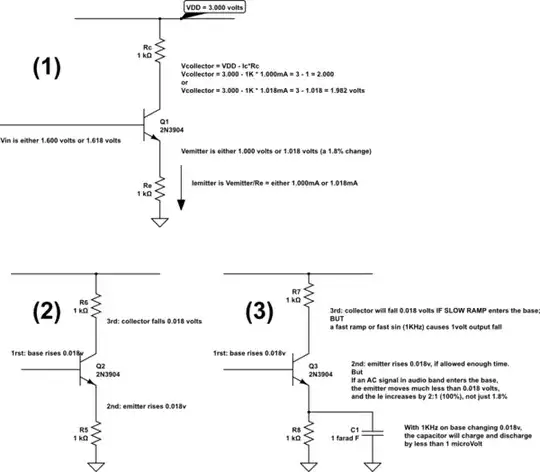
Examine this schematic, where gain is set by 3 effects.

In (1), gain is set --- almost exactly --- by ratio of Rc/Re.

In (2), we summarize the changes in Vbase, Vemitter and Vcollector, showing gain is 1.000.

In (3), we install a huge capacitor, so the change of Vemitter becomes nearly zero (less than 1 microvolt, or 0.000,001 volts) at 1KHz within the audio band. The gain increases, set by Rc/reac where 'reac' is the slope of the diode equation for Vdiode/Idiode of the emitter diode) from 1.000X to 51X.

Why does the change of Vemitter become nearly zero? A 1 farad capacitor needs 1amp for 1 second, to make Vcap change by 1 volt. If we only have 1mA for 1/1KHz time, we'll see less than 1 millionth of a volt change.

I chose 0.018 volts because e^0.018/0.026 is 2.000X larger, and my emitter current will predictably increase from 1mA to 2mA. The diode is non-linear, so the predicted gain of 50X is not achieved; I expect 39X.

Have fun.

schematic

simulate this circuit – Schematic created using CircuitLab

analogsystemsrf
  • 33,703
  • 2
  • 18
  • 46
  • thanks for your effort i really appreciate but i did not understand. i just need to know how the by pass capacitor affects the ratio (peak to peak Vce/peak to peak Vbe) – Alex Jul 18 '17 at 11:01
0

Simplified explanation: For AC signals, the input voltage appears directly at the emitter. Thus the emitter current is given by Vs/Re. Since the emitter current is close to the collector current, the voltage across Rc is simply (Vs/Re)*Rc and is the output voltage. Thus the voltage gain, Vc/Vs, is Rc/Re. If you now bypass the emitter resistor with a large capacitor, the effective emitter impedance become the parallel combination of Re and the capacitor (much less than Re). Thus the emitter current will rise and the voltage gain will also rise given by Rc/(effective emitter impedance.

Barry
  • 15,733
  • 1
  • 26
  • 28
  • Barry - I am afraid, the questioner is not very familiar with the transistor properties and - hence - cannot follow you (why the input signal appears at the E node ....and what is the "effective emitter impedance"?). Why not using the most important transistor parameter (transconduxctance gm) for explaining the properties of the circuit? By the way: "effective emitter impedance" is a wrong term. Such an impedance does not exist at all. – LvW Apr 09 '18 at 14:23