It doesn't look like it works as you suppose.
- At max voltage we get \$ P = VI = 62 \times 1050m = 65\; W \$ as specified.
- It appears that the output is rated at 1050 mA maximum so the highest power you can get at 12 V is \$ P = VI = 12 \times 1050m = 12.6 \; W \$. (1/5 of the power at 1/5 of the output voltage.
This disappointing news can be explained somewhat by a look at the block diagram:
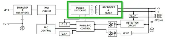
Figure 1. The SMPS block diagram.
Notice that the area in the green rectangle has to be designed to carry a certain current. In this case it is designed to carry a little over 1 A max on the low-voltage side. For it to work the way you expected it would have to carry 5 A in the transformer secondary, the diodes, etc.
The supply is rated as a constant current design and it's main market will be LEDs - with the possibility of dimming by adjusting the control input.
Note that the voltage is not adjustable - only the current. The voltage will rise and fall as required to maintain the set current.
These PSUs have an interesting dimmer control input.
Built-in 3 in 1 dimming function, IP67 rated. Output constant current level can be adjusted through output cable by connecting a resistance or
0 ~ 10Vdc or 10V PWM signal between DIM+ and DIM-.
To do this the controller input is probably something similar to the circuit below.
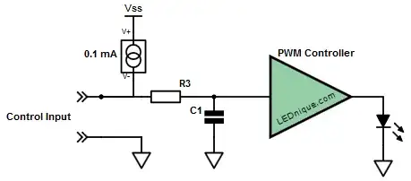
Figure 2. PWM controller input.
- For DC voltage control we just apply the voltage, it gets to the controller with a slight lag depending on the R3/C1 delay and output power is set.
- For PWM a pulse train would be used as shown in Figure 3. This time R3 and C1 filter the PWM to obtain the average DC value. Output power is set as before.

Figure 3. PWM signal transitioning from high pulse width (75%) to low (25%) and back again. Note amplitude remains constant.
- I don’t know for sure, but if the PSU is able to sense a resistance connected to the input then it must be supplying a current to the input terminals as shown by the constant current source. We know that 100 kΩ gives full brightness so that means the voltage drop across the 100 kΩ is 10 V and I = V/R = 10/100k = 0.1 mA.
This theory is supported by the fact that if you use one pot to control multiple fittings that the required pot value is 100/n where n is the number of lamps. This makes sense as each PSU will drive 0.1 mA into the pot. So for five lamps in parallel on the one pot R = V/I = 10/0.5m = 2 kΩ.
• Finally, if nothing is connected the 0.1 mA will charge C1 to 10 V and give 100% brightness.
It’s simple and flexible.


