7

I'm looking at different bridge rectifier circuits and found this one. Capacitors C5-C8 are smoothing capacitors. Both positive DC and negative DC have capacitors C1-C4 linking to both AC lines.

What is the function of C1-C4?

schematic

simulate this circuit – Schematic created using CircuitLab

  • 4
    It's just language, but language shapes the way we think. So although those diodes are 'linking to both AC lines', a better way to describe it is that 'each rectifier diode has a capacitor connected in parallel with it'. This helps bring out the fact that the capacitors are 'short-circuiting' the high frequency output of the diodes when they switch. – Neil_UK Jul 09 '17 at 04:58
  • Very true! It's interesting, I was thinking more about the function of the connections to the rectifier, not necessarily the fundamental structure of the diode bridge. Maybe using the abstract symbol with AC lines and positive/negative output rather than the diodes makes it harder to understand. – Ashton Snelgrove Jul 12 '17 at 21:04
  • Yes, a symbol is a model, which abstracts out a useful simplification. Sometimes, the level is too simple, and it helps to push into the symbol to see the next level of detail down. So here, the caps would go right on the diodes, to minimise the radiating HF current loop area, rather than on the AC lines at the transformer perhaps. – Neil_UK Jul 14 '17 at 03:57

1 Answers1

7

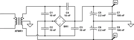
Those extra small value capacitors are to avoid the rectifier generating RF interference.

When a diode has been conducting and then current reverses it can stop conducting very suddenly when the charge carriers are depleted. This can occur extremely rapidly and generate interference to many MHz.

These sudden changes in current can cause interference to other parts of the circuit or even other equipment. It is modulated at 60Hz or 120Hz (US power frequency) so would be heard as a buzz in audio equipment.

The usual avoidance technique is as shown in the circuit. Ferrite beads may also be required in stubborn cases.

The technique can be used intentionally to generate high frequencies or narrow pulses, especially when high frequency devices are not easily available.

Step Recovery Diode

Kevin White
  • 32,097
  • 1
  • 47
  • 74
  • 1
    What you wrote is basically right, I just believe you overestimate (a lot) recovery speed of normal power diodes, nanoseconds up to around 500ns are what is classified "fast recovery diodes" which are going to be used in fast switching application. In mains frequency realm standard recovery diodes (mostly undocumented trr but microseconds and up range) are mostly used due lower cost and forward voltage drop. Infact, due to technology, decreasing trr basically increases Vfd so, summing conduction \$\propto V_\text{FD}\$ and switching losses \$\propto t_\text{rr}\$ a tradeoff has to be spot – carloc Jul 09 '17 at 10:26
  • 1
    You're right, that was rather an exaggeration. I have heard reports that the spectrum extends high enough to interfere with FM receivers (although it may be into the IF at 10.7MHz) – Kevin White Jul 10 '17 at 00:56