I'm trying to build a low power door monitoring switch. I'm using an MSP430FR2311 with the below circuit. The switch is a SPST reed switch and there is an internal pull-down resistor on pin P1.0 of the MCU.
When the switch is open power consumption is 1 uA but when the switch is in the closed state consumption is 100 uA. I want to be able to run this on a small battery for years at a time. Is there a circuit that will get me low power consumption in both the open and closed states of the switch?

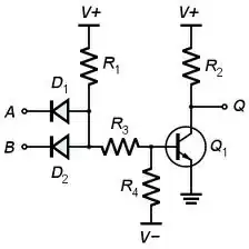
simulate this circuit – Schematic created using CircuitLab