A proportional valve acts more like a linear motor than a relay, so trying to drive it with that strategy will not work.
If you use a circuit as suggested here and here, you will find it impossible to use low opening setting:
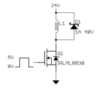
The problem with a simple diode across the coil is that you use the full current rating (in your case 85 mA) when the switch is on, and there is a long delay from 85 mA back to zero mA. That is not the way to drive a proportional valve.
One integrated solution I've used to drive fluid injectors down in the ms range is the ON NUD3160 driver. This provides very rapid dissipation of the stored energy by using a Zener clamp but using the driver FET to dissipate the majority of the power.
You can read more details here on the MOOG proportional valve to understand the mechanics inside. More details (but still brief) on your valve is here.
If you want to persevere with PWM drive (it's simple to implement with an MCU after all) then you need to replace the diode across the coil with a diode in series with a Zener. This allows you to dissipate the energy stored in the motor coil much more rapidly. I'd suggest that you should use a Zener at least twice your supply voltage.... in your case something around a 56 V Zener will help. The PWM rate will depend on the time it takes to dissipate all the could energy, though I'd suggest you won't want to go above a few kHz.
A schematic might be as follows:

simulate this circuit – Schematic created using CircuitLab
Here's a link to a commercial proportional valve driver ....notice that it uses PWM followed by a low pass filter and does current sensing in the valve solenoid.
Additional Info from comments
Given that you are using an Arduino directly, here's a suggested driver methodology.
Using 24 V, 165 mA and your measured 115 Ohm actuator on the valve.
The datasheet for the valve shows that there is an offset current before you get any movement of the bobbin and flow rate depends on pressure. However 100% open corresponds pretty accurately with the 165 mA current flow since this depends almost totally on the spring pressure.

I'd suggest the following schematic:
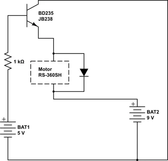
simulate this circuit
You need a FET with about 3-4 V VGS(th) or less.
You can select a device with low VGS(th) from Digikey or the like (such as the ON IRL520 for example) or you could select from what you have using a simple test.
You need to be able to support more than 200 mA into 6 Ohm with the limit of 5 V available from the Arduino.
A simple test setup might be as follows (and remember that the FET will get warm):

simulate this circuit
R2 - C1 form a low pass filter that provides less than 300 mV ripple from the 980 Hz Arduino PWM. You can set this higher or lower if you want, and you can set the PWM frequency higher by altering the timers.
The A/D input is feed from the current sensing resistor and this allows you to set the port high (AnalogWrite(255)) which allows you to saturate the FET and measure the valve resistance from the voltage over R1 (AnalogRead()).
From this you can now calculate the voltage required (on R1) to get any current you want through the valve. You then program your PWM to set the current.


