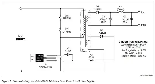
It is a switching power supply. The transistor (probably in the control IC) turns on, pulling current through the primary. As I understand it, this stores energy in the transformer (don't ask me how!) and when the current stops flowing through the primary, it appears on the secondary multiplied by a ratio determined by the number of turns on each side. This current is stored in the capacitors on the output, and you get a DC output.
It's this energy storage and release that makes the design so simple and you find flybacks in almost any modern low power electronics designed to plug into mains power. You don't tend to find them in higher power applications because beyond around 40W they are inefficient compared to other designs, but they are very good for <=40W and used almost exclusively.
It's like a normal mains transformer, but to keep the size and cost down, it's much, much smaller, and operating at a much higher frequency.
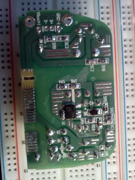
However, it isn't a stunning example of SMPS wall warts to be honest:
It appears this PSU has no feedback loop as it doesn't have an optocoupler for a control signal. It could be using the Vcc rail to regulate, but that is rare...
In a discontinuous flyback (which this almost certainly is) the capacitors take almost all the ripple current. Those caps are far, far, far too small to handle a ripple current of 700mA. Maybe 50mA each on a good day.
Especially notice the tiny primary capacitors, which look like 4.7µF or so each; this may just about be enough for a supply with a feedback loop, but is completely insufficient if there is no feedback loop (there will be considerable 100/120Hz hum on the output.)
Also notice the lack of essentially any line filter, meaning any claim to CE/FCC/etc compliance (required to sell in most countries) is probably forged.
They cheap ones are often unsafe too, but you can't tell until you dissect the transformer. Some really cheap ones are too good to be true.