I am working with a PIC micro-controller with inbuilt 10bit ADC and want to measure a voltage in the range of -1 to -3Volts.
I thought of using an op-amp in the inverting mode to make voltage positive and then feed it to the adc of the microcontroller however here I would have to power the opamp with a negative power supply, right?.
I don't want to use a negative power supply at the moment and was wondering whether it was possible to achieve this configuration?
Can you'll help out?
Asked
Active
Viewed 5.6k times
50
tyblu
- 8,167
- 6
- 40
- 70
Kevin Boyd
- 1,971
- 4
- 23
- 28
-
1the -1 to -3V that I'm measuring is the output of a LM337 that I want to monitor. – Kevin Boyd Jun 21 '10 at 06:23
-
related: [Measure -20V to +20V voltage with pic](http://electronics.stackexchange.com/questions/15940/measure-voltage-with-pic) – davidcary Jun 25 '11 at 22:29
-
I don't have enough details to flesh out a complete answer, but if your PIC has a VREF- (negative reference voltage) pin then you can probably do this directly, without an additional inverter, through creative use of the reference voltages. – Sparr Aug 16 '13 at 02:04
7 Answers
45
An inverting amplifier does not need a negative rail to invert the voltage.
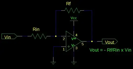
Try to think of your power rails as what supply your output. If you look at the circuit, all op-amp pins are tied to a voltage of 0V or higher. When your range of -1 to -3 comes in, it will show up as the exact opposite of 1 to 3 on the output. This also gives you some advantages as a buffer, as the input impedance of your pin will not affect this circuit very much (so long as Rin||Rf is large).
I agree that a simple resistor divider does the job -- just letting you know that this also works.
-
2+1 -- this is the proper way to do it if you don't have an ADC taking in negative inputs. – Jason S Jun 20 '10 at 19:41
-
1Wow!, this is fantastic!!, is there some datasheet gotcha, that the input should be only so much negative than the voltage level that powers the negative rail of the op-amp? – Kevin Boyd Jun 21 '10 at 06:22
-
3No, the rails of the op-amp are the bounds for your output. Where a rail to rail op-amp will go very close to the bounds. You could, and many have, spent their life designing op-amps. There is no such thing as a perfect op-amp, but there is normally a perfect op-amp for a specific case. – Kortuk Jun 21 '10 at 14:03
-
4On that note, in this configuration, if you surpass around -Vcc as your input your output will hit the Vcc rail. Some op-amps will not go within a volt or more of the rail, some op amps will go within 50mV. If you get a larger input signal, divide it by a larger amount, if you have a -1 to -10 V signal, divide by 2, problem solved. – Kortuk Jun 21 '10 at 14:04
-
2@Kortuk - There is is never a perfect op-amp for *any* case. However, there is the best op-amp out of the available selection, when price is taken into consideration, for every project. – Connor Wolf Oct 19 '10 at 04:27
-
3@Fake Name, I think this is a case of a communication error. If it meets the specs you need and is affordable then you have the perfect op-amp. That would be my wording, I understand what you mean though. I accept the limitation and use perfect because I am positive. <3 – Kortuk Oct 19 '10 at 14:36
-
1@Kortuk - I'm being pedantic. Perfect is *never* possible given we live in reality. it can only be aspired to. – Connor Wolf Oct 20 '10 at 05:25
-
2@Fake Name, One of the definitions of perfect is satisfying all requirements. If everyone gets what they need, then you have a "perfect" solution. – Kortuk Oct 20 '10 at 14:01
-
1@Kortuk - Wow. Apparently my requirements are more stringent. I never have anything that satisfies *all* of my requirements, just enough that it works. – Connor Wolf Oct 21 '10 at 08:17
-
Haha. I will accept that. I follow the idea that if the customer is happy and the system is maintainable, then it is perfect. – Kortuk Oct 21 '10 at 18:58
-
1
-
@Kortuk I don't know, but it seems that this scheme has got messed up for some reason, or it's my browser; I cannot see it properly. – clabacchio Feb 14 '12 at 14:13
-
@Kevin: I think what you're missing (and this answer didn't really explain) is that the input pin of the op-amp will be held at zero, so it won't exceed the allowed range. There's a voltage drop across both Rin and Rf, so Vin is not seen by the op-amp. – Ben Voigt Feb 22 '12 at 19:57
-
@BenVoigt, Yes, I realize that I stated it but did not take the time to explain. Sorry about that. – Kortuk Feb 23 '12 at 01:15
-
What happens when the input voltage goes below the negative rail though ? – Mike Apr 07 '16 at 18:04
-
@Mike That's exactly what the whole answer and all the comments explains. Not sure how it's possible to explain it further. – pipe Apr 07 '16 at 20:03
16
You could use a voltage divider, with one end hanging off the positive supply rail. Say you have one with equal resistors and a 5V power supply, this will result in a voltage between +2V and +1V for your -1 to -3V range.
+5V +
    |
    R
    |
    +-- OUT
    |
    R
    |
IN -+
Wim
- 432
- 2
- 7
-
4This will require the IN terminal to sink a current of (5-Vin)/(2R), so you'll have to choose R large enough to not overwhelm the input with unwanted current. then, your ADC input will need to have at least an order of magnitude more input impedance than the R value, in order not to unduly load down the divider network. Which all may (or may not) be possible. To the data sheets! – JustJeff Jun 20 '10 at 13:35
-
3-1: you'd better use precision resistors and a precision reference for 5V. – Jason S Jun 20 '10 at 19:39
-
2+1 for being the cheapest simplest way. But as Jason S says, precision will take effort, if that matters. – DarenW Oct 15 '10 at 20:34
-
4
-
If reference voltage is not present (e.g. MCU is not powered up) input may go deep minus in regard to the ground, damaging the input or MCU in whole. – Anonymous Nov 06 '20 at 07:42
7
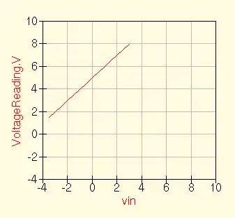
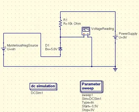
The voltage divider idea is nice, cheap, but gives you the problem of a change of the voltage to be measured will be seen as 1/2 the change at the ADC input. If accurate measurements are of interest, the solution is a zener diode as the bottom half of the divider. If the thing being measured can tolerate losing a teeny bit of current, this will work great. Zeners aren't absolutely flat in their reverse breakdown voltage, especially for very small currents, so don't make R1 too big.
Now to see if this stackexchange site allows me to add images...
DarenW
- 4,060
- 1
- 23
- 37
4
This is the standard circuit for that sort of conversion. I simulated it to prove to someone that it worked, hence the SPICE schematic. You need to choose appropriate resistor values, it works as long as they are 2R, 2R and R.
Leon Heller
- 38,774
- 2
- 60
- 96
4
I'm at (non-electronics) work right now, w/o handy electronics sw or books, so this will be just a rough idea. Maybe someone else can fill in the details...
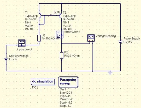
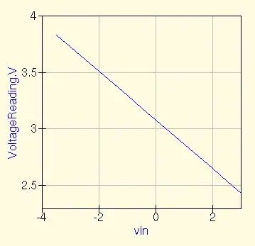
Try a current mirror using a pair of PNP transistors hanging on the Vcc rail. Feed the negative voltage signal to the input side of the mirror through an appropriate resistor. The same current should then flow through the output transistor of the mirror. With a well-chosen resistor you create a voltage range within 0V to Vcc.
EDIT - NEW: Here is the current mirror schematic. Whatever current passes through transistor T1, T2 will try to make the same current flow. The negative voltage to be measured, relative to the power supply which I randomly chose to be 15v, creates some trickle of current through R1 (measured in simulation as "inputcurrent"). If R2 were the same as R1, you'd find the same voltage across it, if it were allowed to. But it's connect to 0V (gnd) - our circuit is based purely on a positive supply. It won't work unless we make R2 smaller, say 1/2 of R1 then the voltage across it will be 1/2 of whatever's across R1. Measure it, do math (whoo, multiply by 2, hard!) and there you are. The schematic has different values, a different ratio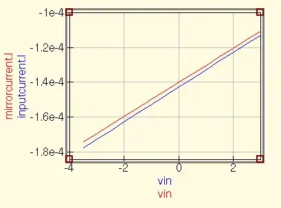 , but I think we all can handle the math for this.
The advantage of this over a simple voltage divider is that 1) it looks more complicated, 2) it's a common trick in analog IC design. Since I wrote another answer using a Zener diode, I'm not sure now why this is better, but it is an alternative to a voltage divider and may allow getting at different ranges of voltages or something. Now I let others comment on the wisdom or foolishness of this idea...
DarenW
- 4,060
- 1
- 23
- 37
-
I couldn't understand what you meant here, a link to a schematic would help. – Kevin Boyd Oct 18 '10 at 12:22
-
Okay, i've got time now...and as I think about it, I'm not sure why it's better than some simpler circuits except as the detailed design might work out better numerically, perhaps. Schematic will be attached soon. – DarenW Oct 19 '10 at 03:23
-
Old question I realize, but... This circuit relies on the base-emitter voltage vs collector current curve of the two transistors being the same, so that the same current flows in each of the two transistors collectors. That would be a good assumption in an IC where transistors can be made to match well, (and are at the same temperature), but not for two discrete transistors. The circuit can be made less sensitive to this problem by putting matching resistors in series with the emitters. – gwideman Mar 06 '13 at 04:44
0
You might not even need an op-amp. Some ADC's (like the MCP3304, see datasheet: http://ww1.microchip.com/downloads/en/DeviceDoc/21697e.pdf have a built in differential mode, where the ADC returns the difference of two channels, which can be a negative number. If you tie one channel to ground (called pseudo-differential mode), the ADC can accept a negative input voltage on the other, and translate it into a negative number, all without needing a negative voltage.
Of course, this only applies if your ADC supports this sort of thing. Many don't have differential mode at all.
dpdt
- 1,707
- 16
- 26
-
3Have you checked the datasheet on this part? From the sheet in the absolute maximum ratings section: "All inputs and outputs w.r.t. VSS ............... -0.3V to VDD +0.3V" That means you can't have a negative voltage on the inputs or any other pin for that matter. Why? because the input protection diodes will turn on and prevent the part from being burned up. This does not answer the question, the question was how can I measure a negative voltage? You can't measure a negative voltage with this part. – Voltage Spike Apr 07 '16 at 22:51
-2
I think there are already very good answers, but I like to post another approach, that I am using myself to do basically the same thing.
You could use an instrumenting op-amp (like an LT1167)? You would however need the negative rail, but wouldn't this give more accuracy? and also better ways of amplifying the voltage if wanted by simply adding one resistor.
adding the negative rail is as easy as adding something like a minmax MCW03-05D05.
The problem I have with using resistors is that it is very hard to find identical resistors, which would give you an error you'd have to correct.
Nisse
- 109
- 1
-
-
-
1You said yourself that the resistors are the primary source of the error. Using a more expensive part, along with needing to add some kind of negative rail, does not fix that. Using resistors with higher precision makes more sense. – Matt Young Aug 16 '13 at 03:37
-
well, if there is no need for amplification there is no need of any resistor.. Also it's just another way of doing it, I'm not saying it's the right way to do it for any application, but in some cases it might be better to give up on not using a negative rail. – Nisse Aug 16 '13 at 09:32