5

I am conducting a scientific experiment to approximately measure the entering velocity and the leaving velocity of a magnet through an electromagnetic coil.

Beside the coil are two lasers and two LDRs as depicted by the figure below.enter image description here

I expected this circuit to generate a rising edge and a falling edge, but I realized only after testing on the oscilloscope that I was not able to receive a square waveform to input to my MSP430 MCU as interrupts. My plan was to calculate the time between these two interrupts.

However, the waveforms I observed were as below. enter image description here

Then I thought that I could use an LM358 in front of my voltage divider. This is described in here. But looking at my practical waveforms I observed from the oscilloscope, I am doubtful how I can tune the comparator. Is there a better way to achieve my task using better electronics? I am not limited by component costs, however, I am not willing to buy a ready-made apparatus for this purpose. My intention is to develop one.

Thank you for your views and help.

donjuedo
  • 161
  • 3
  • 7
Denis
  • 1,245
  • 3
  • 17
  • 35
  • 1
    How can you be sure the magnet doesn't just like the applied mag field so much it sticks in the middle? Basically I'm questioning the experiment. – Andy aka Jun 12 '17 at 13:21
  • 7
    Among EEs LDRs are "famous" for being **slow**. Before "fixing" your circuit, test with the LDRs on their own and check if they respond quickly enough. If not, look at photo diodes/transistors. – Bimpelrekkie Jun 12 '17 at 13:22
  • 1
    How are you going to keep you magnet in a straight line so that velocity can be accurately calculated? What about optical reflections from the magnet giving a false image on the photo detector? I smell problems here. – Andy aka Jun 12 '17 at 13:26
  • 1
    What timescales do you believe you need? – Chris H Jun 12 '17 at 13:37
  • @Chris H, the oscilloscope says the time between rise-up and fall is 10mS. I must find a light detecting component that can support that 10mS or faster change.. – Denis Jun 12 '17 at 13:41
  • 1
    So slow in terms of photodiodes/transistors but fast in terms of LDRs (75ms rise, 350ms fall from [*Sensors and Transducers*, Ian Sinclair](https://books.google.co.uk/books?id=s_WIb91uKK8C&pg=PA65&lpg=PA65&dq=LDR+rise+time)). But note that your traces seem to be based on the LDR, and seem to be faster than than the figures from the book (which may be a worst-case component). – Chris H Jun 12 '17 at 13:44
  • That is true. But I actually saw a rise-up and a fall down within 10mS using a cheap LDR. I am certain about it. Perhaps over time, LDRs have improved? can that be a possibility? Anyway, the LDR method doesn't seem to serve the purpose. I am ATM going through photodiodes/transistors. I wish to order one right away and test the same circuit again. As @Bimpelrekkie suggested, I should first change my LDR. Then I can worry about other problems. – Denis Jun 12 '17 at 13:55
  • 1
    Smaller LDRs may be faster than larger ones; different materials and different resistances will behave differently. Many optoelectronic components can be encouraged to give a faster apparent response than the datasheet suggests -- and this might even work for you if you don't care about the shape of the signal. What does classical mechanics suggest you should get? – Chris H Jun 12 '17 at 15:46
  • 2
    Also **S** = Siemens (conductivity), seconds are **s** – Chris H Jun 12 '17 at 15:46
  • 2
    I have worked on a similar project in which the coils were used to do this. Use the coil to make an oscillator that is precisely matched with a second oscillator constructed with an equivalent coil. Mix the two signals with one through a 1X inverting amplifier, as the magnet enters the sense coil, the resultant amplitude will become positive. This can then be used to trigger a timer/counter. and you may use each crossing to determine the velocities since the starting gravitational potential energy of the magnet is known in reference to the sense coil . Optics proved to be troublesome for us. – Luke Gary Jun 12 '17 at 16:35
  • Hello all, I did make the optical as well as the microcontroller circuitry for this. The circuit works so well. Results are so close to the theoretical values. Right now, the whole system looks like a mess. I will post as an answer all the circuitry and the source code I used for this project within several days – Denis Jul 19 '17 at 07:27

3 Answers3

15

LDRs are slow. Consider using a photodiode or phototransistor instead.

LDRs have slow response times, their resistance changes slowly, and that is probably what is causing the slow response of your system. Photodiodes and phototransistors are both light-sensing components with faster response times. They are a little trickier to use than LDRs, but not too bad. Have a look at some datasheets for both, they will have recommended circuits in.

Jack B
  • 12,167
  • 1
  • 27
  • 46
  • 1
    A phototransitor in particular would be quite easy to set up. – Chris H Jun 12 '17 at 13:36
  • 2
    Phototransistors turn on quickly, but they turn off slowly. Therefore, you will get faster timing when the object leaves the beam, rather than when it cuts off the beam. Simply make sure your micro uses the fastest edge. Check out this document http://www.cel.com/pdf/appnotes/an3009.pdf with various phototransistor configuration and their speed. Cascoding seems to help. – bobflux Jun 12 '17 at 13:58
  • 1
    If ambient light is a problem, you could use modulated light too. Something like an IrDA receiver, or anything with high enough bitrate should provide a nice off the shelf solution. – bobflux Jun 12 '17 at 14:01
  • Yes surely. Although what you said needs to be incorporated very carefully I remember the times we used to build line following robots which were immune to changes in ambient light. Basics are so important! – Denis Jun 12 '17 at 14:28
  • Dear Peufeu, I have a problem there! I want both times! i.e. I want an interrupt as was it enters as well as when it leaves. Would that be a problem? Shouldn't be a problem, as long as I buy a photo transistor of very high speed. Am I correct? – Denis Jun 12 '17 at 14:31
  • @peufeu these times are slow compared to semiconductor optoelectronics. A [BVP11](https://www.vishay.com/docs/81504/bpv11.pdf) phototransistor will give you a few µs up and down and can easily drive a logic-level input. I'm more used to photodiodes for the 10s to hundreds of ns region. You can also get filtered photodiodes and phototransistors to match your laser. – Chris H Jun 12 '17 at 15:51
  • I'm gonna write it as an answer, because this will be too long for a comment... – bobflux Jun 12 '17 at 16:16
  • problem with ambient light (sunlight or incandescents) is the risk of full-on operation of the phototransistor. I prefer 3-terminal phototransistors, and I regulate the base thru a highvalue resistor andcap to gnd and a 2nd highvalue resistor ("T" filter), to hold collector at VDD/2. – analogsystemsrf Jun 12 '17 at 16:23
3

Consider something like this, to tolerate sunlight

schematic

simulate this circuit – Schematic created using CircuitLab

analogsystemsrf
  • 33,703
  • 2
  • 18
  • 46
  • Dear all, I am updating my result as a comment here. I made this circuit 1 ( the one of left hand side) work by removing the R2,R3 amd C1. i.e. Base terminal is not connected to anything. It accurately measures the drop!!! I just used a normal 1$ laser. Thank you so much for everyone who spent valuable time on this! truly appreciate it. – Denis Jul 17 '17 at 11:24
  • Please expect an answer from me for this question within several days. In that I will post all source code, hardware wiring diagrams so that anyone can replicate this work within a day or two. I think that the best way I can give back for what you all have given to me. – Denis Jul 19 '17 at 07:13
3

Complement to Jack B's answer:

BVP11 seems much faster than the phototransistor in the link I provided, although I don't know if they measured it using a simple resistor load or a cascode.

So, the phototransistor should be selected for speed.

Good idea using a filter to match laser wavelength and get rid of ambient light. You can also put the transistor inside a long enough opaque tube with blackened internal surface to block ambient light.

Now, you got 2 sensors, so when the object passes, both will generate a pulse. This pulse has 2 edges (on/off).

If the object is shorter than the distance between sensors, you'll get:

    1. sensor 1 dark
    1. sensor 1 lit
    1. sensor 2 dark
    1. sensor 2 lit

This should be pretty obvious. If the object is longer than the distance between sensors, the order of events will change, but it matters little.

I wanted to attract your attention to the fact that rise and fall times will not be identical, therefore if you measure the time between two edges, make sure they're in the same direction. For example, you can measure the time between both rising edges, or both falling edges, and if the phototransistors have the same speed (you should check) then this will not introduce error.

Now, since you want the magnet's speed, you will be measuring the length of the pulse instead (rising edge - falling edge). If both phototransistors are identical, this will work, but if their rise/fall times are not matched, pulse lengths may be different even though the speed of the magnet stays the same.

I wanted to make sure you were aware of the inconvenience.

Also, if your phototransistors are not matched, or they are at different temperatures, or if the amount of light reaching them differs, then the output current will be different. If you use two dumb comparators with the same threshold, this threshold will be crossed at different points in the two waveforms, and this will introduce an error in the measurement of flight time between sensors. Laser light output may also vary with temperature.

A simple way to solve this problem would be to calibrate the DC level out of the way, by using a circuit like this:

Feed the phototransistor output current into a transimpedance amplifier (ie, a simple opamp). This gives you a voltage and allows the phototransistor to output into a virtual ground, which will mitigate its output capacitance and make it faster. Now, AC-couple (ie, highpass) this voltage to remove the DC light level which corresponds to constant illumination by the laser. Use a hysteresis comparator to detect your pulse's edges.

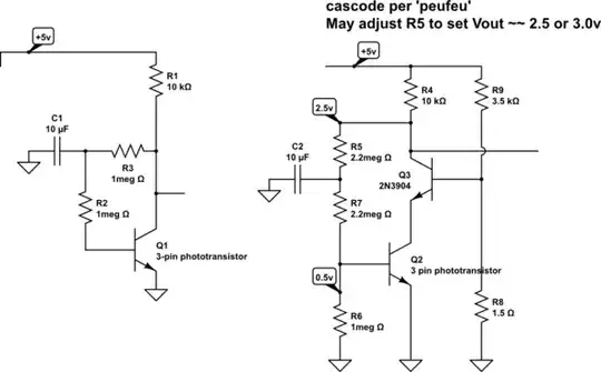
analogsystemsrf's answer is also excellent! (you can even cascode the phototransistor).

You could use two pairs of sensors instead, each pair measuring speed. In this case you'd measure time between two rising edges, so rise time asymmetry would be less of a problem. Spacing them a little bit more would also improve accuracy.

Another option would be to use modulated light in the MHz range or above, but this is more complex. If you repurpose something like an IrDA or fiber optics receiver, its internal AGC could mess things up.

I would suggest calibrating the system by shooting something which has the same shape as your magnet, but is not magnetic, like a piece of black plastic. Normally it should have the same speed on entry and exit, so you can be sure you're measuring the right thing.

bobflux
  • 70,433
  • 3
  • 83
  • 203
  • THank you so much for your kind efforts Peufeu! I am at the moment going through all suggestions provided by you. You have spent so much time searching my my task and providing me with these valuable suggestions. Everyone here is so helpful. This sort of help is very rare where I live. I sincerely hope you find the same when you're in need. – Denis Jun 13 '17 at 06:07
  • You're welcome! I wish you success, and maybe post the finished schematics to help others if you're allowed to ;) – bobflux Jun 13 '17 at 15:52