I'm laying out the PCB for a small and simple power supply to feed some audio amplifiers. It will feature a DC -DC converter module and I'd like to filter the output for 1) extra smoothness 2) learn about power supply filtering. So I found this courtesy of TI:-
I'm using a TRACO converter rather than TI, but otherwise the circuit is the same. The switching frequencies are similar. They're both 2W - 3W power. So a 100uH ferrite inductor looks like:-
If I were to have a ground plane on the backside of the PCB, do I back it off from the inductors (and converter)? Consider that there will be inductors inside the converter. That's three inductors. Do I put three holes through my ground plane, or keep it solid?
I looked at one question that suggests keeping the ground plane solid, whilst the answer for this one suggests a hole. I'm confused again.
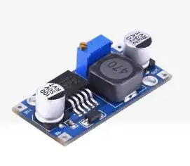
Further confusion arises from some cheepo converters I have from on-line. You'll have probably seen one of these fairly ubiquitous thingies:-
These have a solid ground plane on the reverse side. Is that just 'cos it's easy /simpler or are cutouts unwarranted? Clarification would be most appreciated.


