18

What's a good circuit to use to generate a square wave? The exact waveform isn't too important - I just want to get a piezo buzzer cranking at 150 kHz. I also want efficiency and adjustable amplitude.

(Motivation: I want to vaporize some oil in order to burn it. I choose 150 kHz after the Glade Wisp as hacked in Make.)

The simplest I found was this one consisting of a capacitor, 3 resistors and an op amp a comparator. Is this design a good way to go?

Assuming so, according to the same page, it has a period of

\$T = 2RC ln \dfrac{1+L}{1-L}\$ where \$L = \dfrac{R1}{R1+R2}\$

Choosing R1 = R2 gives L = 1/2, giving (1+L)/(1-L) = approximately e, giving the simpler

T = 2RC

I'm in the woods here, but I'll suppose that R1 = R2 = R is a good choice.

The T I want is 1/150kHz; thus RC = 3.33e-6

Another abitrary choice presents itself. Say, a 100 ohm resistor and a 0.033 uF capacitor? Is this choice important? Is choice of op amp important?

Sorry for the long question, but if someone who knows what they're doing could walk with me here, I'd surely appreciate it.
Bruno Ferreira
  • 4,470
  • 2
  • 25
  • 36
Grumdrig
  • 505
  • 4
  • 12
  • 3
    I'll add just a little more explanation, as requested by @Lou. My goal is to build an olive oil burner suitable for lightweight backpacking use. I don't know if this is going to work but it's an idea I want to try. This would turn olive oil into a multi-use item, burnable by me and my stove. It has higher energy content per oz than alcohol but its flash point is too low to burn as liquid at normal temps. So my idea is to vaporize it ultrasonically & burn the vapor. – Grumdrig Nov 10 '09 at 18:02
  • Olive oil burns fine with a wick, but that generally doesn't produce much bulk heat. It'll be more like a small candle. – XTL Jul 21 '10 at 17:12
  • Yeah I know. It's not really enough to cook anything and combustion isn't very complete. (Soot is produced.) – Grumdrig Jul 21 '10 at 21:04

8 Answers8

26

If you google for 555 square wave generator you'll get thousands of hits for circuits based on a 555 chip that produce a square wave. There's a square wave calculator here, which should allow you to experiment with the calculations.

Plus as an added bonus 555 chips are dirt cheap.

Or look at 556 chips which are basically two 555s on the same chip.

Amos
  • 2,893
  • 3
  • 26
  • 26
18

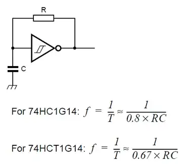
For a simple oscillator people often think immediately of a 555 timer IC. This ciruit is even simpler:

Oscillator

The 74HC1G14 is the single gate version of the more common 74HC14 in SOT-23 package.

stevenvh
  • 145,145
  • 21
  • 455
  • 667
11

Please note: the circuit you linked to uses a comparator, not an op-amp. You can use op-amps in comparator circuits but they aren't up to the job for various reasons: op-amps are optimized for amplification applications where the inputs are driven to the same voltage through feedback, and may take a long time to recover from saturation when their inputs zoom apart through positive feedback like in this circuit. A comparator will be faster and will do the right thing.

As for circuits: I'd either use a LM393 comparator or a 555 (hard to beat: lots of manufacturers and you can get it from Radio Shack or in high quantities from Digikey at 11c) or a 74xx123 (this one from TI is 16c in large quantity). The comparator will need a few more parts than the other two.

Jason S
  • 13,950
  • 3
  • 41
  • 68
8

If you are wanting to build an A-stable vibrator, then the circuit you chose is fine. You will want to keep the R value from loading the op amp. This means selecting R so that it doesn't load an op amp. I would suggest that mean staying in the 10k-100k region of resistance keeps you safe if you use a baseband op amp like a TL072(FET) or an LM358(BJT).

With your circuit you will need trim resistors to get the thing to 'load up' right. A potentiometer in line with R (your feedback resistor) will probably be necessary for tuning.

I think you will find that it is a lot of trouble to make an oscillator circuit this way. I would only do it if you have some very compelling reason not to use a micro controller. A basic stamp, propeller, or Atmel based mcu circuit would be able to create this same squarewave much more accurately. A 555 timer would also work but I would just go the MCU route, an ATtiny 8 pin is 3 bucks so why not just use that.

But multivibrators are fun to play with if you are just playing, remember to buffer the output so you don't load the thing! Good Luck.

Scott Murphy
  • 925
  • 6
  • 10
  • Thanks for this info! The reason I didn't want to use a microcontroller is because I assumed it would be less power-efficient than a simpler circuit. But maybe if the amplification stage is the major power drain, the MCU would be a minor issue. – Grumdrig Nov 10 '09 at 17:51
6

Can't you just use a standard crystal oscillator circuit, like the Pierce oscillator, and drive the piezo at its natural resonant frequency?

Here's a circuit for an ultrasonic cleaner, which would seem to be the same principle as your vaporizer. You can also look at patents for things like ultrasonic humidifiers, atomizer, nebulizer, etc.

No matter what you use, you should have a resonant inductor in series with the piezo to get the hundreds of volts to drive it. http://www.techmind.org/sl/#electric

Surely a microcontroller is overkill when the micro has exactly this kind of oscillator inside it to run the clock. You'd be using a crystal oscillator to drive a computer to drive a crystal oscillator.

endolith
  • 28,494
  • 23
  • 117
  • 181
  • My first attempts to implement didn't do anything to crank up the volts and therefore failed, but I haven't done anything about it yet - thanks for the info - I'll check this out. – Grumdrig Jan 26 '10 at 18:09
5

As advised by @Scott Murphy and @Lou, I'm going to implement this with an Arduino (with which I'm familiar) running into an amplifier. Depending on power consumption it may make sense to switch to some other circuit later, but I'll cross that bridge when I come to it - if the oil burns and power use is higher than it could be. In that case I'll try a 555 circuit or modify the astable multivibrator I mentioned, as advised.

For amplification, for now, I'll use a headphone amp, and put together an op amp circuit if needed.

Will update here as the implementation comes together (or falls apart).

Grumdrig
  • 505
  • 4
  • 12
4

I agree with Scott above: A micro is the way to go here, unless you're just playing about with the specific intention of learning oscillators. Making the amplitude adjustable could be a bit tricky, though. Can you tell us more about that? Does it need to be adjusted once (or very infrequently) for calibration purposes, or do you need to be able to change it frequently? Does it need to be user-adjustable, or will it adjust based on parameters in the circuit? What is the range of the amplitude you need, and the resolution (or rather, how many steps) you need in that range?

The simplest method is to just build an adjustable gain amplifier using a potentiometer for the adjustment, if you only need the amplitude adjustable for calibration purposes or for infrequent manual adjustment.

Another way to make it adjustable is to use the PWM output of the micro and feed that to a filter, but you'd have to build a filter that passed 150kHz and smoothed out anything at your PWM frequency (which will depend on your micro frequency). This will be difficult and will strictly limit your resolution.

If you need a square wave above the micro voltage, you'll definitely need an amplifier circuit, and you can probably just control the gain of the amplifier with the micro as well.

Come to think of it, are you sure you need to control amplitude? You can probably control whatever you are trying to control through other tricks as well. If you could share more information, we can probably give you other control ideas.

Lou
  • 1,829
  • 17
  • 16
  • Thanks for this info too. Wish I could accept more than one answer. The amplitude needs to be adjustable because 1) I don't know how much power I'll need and 2) conditions (e.g. temp) will probably affect the power level needed (though I could probably set it to "high enough" and be done). So it can be pretty coarse and maybe fixed, eventually. – Grumdrig Nov 10 '09 at 17:56
  • @Grumdrig: This is where it's useful to answer the question yourself, mark your answer as a 'community wiki' answer, and then add in all of the good parts from the other answers. By marking it as a community wiki answer, you let others improve the answer over time, while not taking credit for other's work. – Craig Trader Nov 10 '09 at 18:37
  • 1
    I agree with Craig. The thing about electronic projects like this is that the questions asked are usually not atomic, which makes it impossible to pick one answer. Another nice feature of the community wiki is that the answer can evolve as the question evolves, and it makes it easier for people to follow the development of the project. If you are willing, would you post the results of your first shot with the circuit? I'm really interested to see how well it atomizes with an ultrasonic solution, and I'm interested in the backpacking aspects. I'll think of efficiencies while I wait. – Lou Nov 10 '09 at 19:17
  • Thanks @Craig. Didn't know these meta-use subtleties; I'll accept my wikified answer in 36 hours(!) when chiphacker lets me. – Grumdrig Nov 10 '09 at 20:45
  • I've been playing with StackOverflow for over a year; you'll pick it up in time. – Craig Trader Nov 10 '09 at 21:15
  • There's not much in the original poster's history here that suggests he'd be ready to dive into the microcontroller world, which would involve picking a platform, building/buying a devkit, and learning to program it. A timer circuit or oscillator circuit would probably be much more approachable in this case. – Scott Seidman Sep 10 '12 at 14:29
3

If you just want simple gain adjustment, I'd go with the 555 timer. Then use a potentiometer in parallel with a resistor on the output, to create a log pot, (don't buy log pots, they're a rubbish estimation of a log curve, unless you spend mega bucks) the potentiometer set up is here -> https://sound-au.com/project01.htm

If you want accurate control, I'd agree with the other answers, an Arduino type board or an MCU would be much better.

Don't forget, volume is not linear!

I've made an open source pocket oscillator, called a Posc, it features two square waves produced by a pair of 555 timers, have a look, it may help -> http://www.sonodrome.co.uk/tutorials.html There's a couple of PDFs on this page that show the circuit and component layout.

pipe
  • 13,748
  • 5
  • 42
  • 72
Jim
  • 3,325
  • 2
  • 28
  • 39
  • Forgot to mention, the joy of a 555 timer is that it will not require amplification to drive a small speaker or piezoelectric buzzer, however most other oscillators will require amplification with an extra IC or a couple of Transistors. – Jim Dec 23 '09 at 11:58
  • The second URL ("tutorials") is a dead link. – gbarry Sep 10 '12 at 14:45