-2

I have this relay: https://www.amazon.es/dp/B06XD6Q746/ref=sr_1_1?ie=UTF8&qid=1496046490&sr=8-1&keywords=rele+5v

and I want to power this solenoid: https://www.amazon.es/12V-Electroim%C3%A1n-Solenoide-Bastidor-Abierto/dp/B00ICD1OL6/ref=sr_1_2?ie=UTF8&qid=1496046146&sr=8-2&keywords=solenoide

Can someone confirm my plan is correct before I burn my house down?

  • pi +5v to relay module VCC
  • pi gnd to relay module gnd (is 3v3 enough?)
  • pi gpio1 to relay module In1
  • pi gpio2 to relay module In2

  • 12V+ battery pack to relay module middle connector for the rele (com?)

  • simple wire from NO connector in the rele to the solenoid
  • simple wire from solenoid to 12V- in battery pack.

And same approach for 12V led stripes and other 12V stuff.

This would be the schematic, please confirm I didn't omit something when drawing it.

schematic

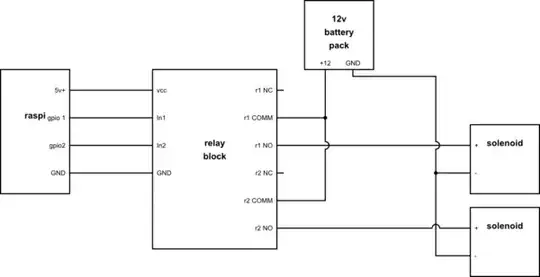
simulate this circuit – Schematic created using CircuitLab

Is that Ok ???

Michel Keijzers
  • 13,867
  • 18
  • 69
  • 139
javirs
  • 185
  • 1
  • 9
  • Draw a proper schematic please. – Andy aka May 29 '17 at 10:27
  • any free online software I can use? is MS paint ok? – javirs May 29 '17 at 10:29
  • There is a built in tool you can use in your question but any method that produces something that looks like a schematic is usually acceptable. – Andy aka May 29 '17 at 10:31
  • There is something wrong IMHO with that relay board. It has optocouplers to "isolate" input signal, but only one GND pin, which makes me thing it is not isolated. Maybe the yellow jumper does something? Too bad that this ebay seller does not provide schematic or wiring diagram. I would not risk to buy a module with so poor description. The market is full of "traders" that have no idea what are they selling. – Todor Simeonov May 29 '17 at 17:13
  • The schematic is right there.. In the second picture. Here: https://images-na.ssl-images-amazon.com/images/I/41E4UHdRG2L._SL1500_.jpg – javirs May 29 '17 at 18:45

2 Answers2

0

The solution seems ok, but you should isolate the relay and raspberry pi to avoid any back fire from relay or solenoid. Consider using this module: https://www.amazon.es/dp/B06XD6Q746/ref=sr_1_1?ie=UTF8&qid=1496046490&sr=8-1&keywords=rele+5v

Prasan Dutt
  • 286
  • 2
  • 15
  • what's the difference between the one I posted and the one you suggest? why is the opto-isolation in the one I posted not good enough to save the pi ? – javirs May 29 '17 at 12:21
  • I hope you understand the importance of isolation between power supply input and output. The separate answer posted by Olin is using a FET with a flywheel diode. The importance of flywheel diode is similar to opto isolation. If you wanted to use FET, olin answer is right fit for you, otherwise use a relay module with isolation option – Prasan Dutt May 29 '17 at 12:51
  • Im provably going the relay path, the question is still .. what's the difference between your proposal and mine ? – javirs May 29 '17 at 12:55
  • In order to avoid explaining the same thing, a detailed discussion and solution for your question is here: https://electronics.stackexchange.com/a/59315/11813 – Prasan Dutt May 29 '17 at 13:24
0

You want to control a 12 V solenoid from a digital output. There is no need to first control a relay, then have that control the solenoid. To the driving circuit, there is basically no difference between a relay and a solenoid.

All you need is two additional parts beyond the relay itself:

This particular FET can be switched from just 0 and 3.3 V. Depending on the state of the digital output, the FET either connects the bottom end of the solenoid to ground or leaves it floating. D1 gives a place for the inductive kickback current to safely flow. Without it, the inductance of the coil would cause as high a voltage as necessary to keep the current flowing in the short them when you try to switch it off. This would fry Q1.

There is no need for any additional isolation between the RPi and the solenoid. Connect the ground of the 12 V supply to the ground of the RPi. This is necessary for the gate voltage of Q1 to be driven properly.

Olin Lathrop
  • 310,974
  • 36
  • 428
  • 915
  • can you give more details on D1, some reference? I guess the diode at Q1 i already part of the IRLML2502. Would same approach (without D1) work for 12V led stripes and others ? (BTW, thanks for the detailed instruction) – javirs May 29 '17 at 12:54
  • @jav: D1 can be any diode that can withstand the open circuit voltage when the solenoid is on, and the flyback current immediately after being switched from on to off. The first is 12 V, but some margin is good. In practice, it will be hard to find a diode that can't handle a bit more than that. The max flyback current is the solenoid steady-on current. The diode maximum pulse rating must exceed that. If you do PWM or might switch on while flyback current is still flowing, as Schottky (as shown) is good due to its fast reverse recovery. – Olin Lathrop May 29 '17 at 14:26
  • 1
    @OlinLathrop the OP already got a realy board (his first link) which includes the transistors and need only TTL logic input. Well... yes, his description is confusing, because he said just "relay" instead of "relay board" :) ... All necessary stuff is placed on this board, and it is even optoisolated. Only a wire is needed between MCU's digital output and this board's input. – Todor Simeonov May 29 '17 at 16:57