2

I've recently bought HD44780 compatible LCD screen (16x2) from eBay. I want to use it with my Spartan 3 FPGA development board, but after I've thought a little about it, I'm not sure that I can use it.

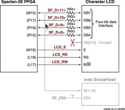
The main thing that's bugging me is that the display that I've bought works on 5V, and all Spartan 3 I/Os can work at max. 3.3 V. So is there any way to use Spartan 3 and this display ? Is it possible that it will work with 0V and 3.3V as logical levels (or does it require TTL levels) ?

I don't have datasheet for it, so I'm not sure. I've searched it physically for some marks, and I've only found this: "1602ZFA", but when I google it, I don't get anything good.

I've also asked the seller to send me datasheets, but I think he sent me wrong ones ... Here's what he sent me:

enter image description here

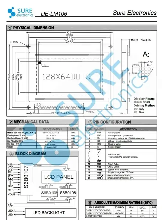
I have only 16 pins on my display.

So, is there any chance that I can use this display with Spartan 3 FPGA ?

xx77aBs
  • 902
  • 3
  • 17
  • 25

2 Answers2

2

The 3.3V will be recognised as a high-level by TTL logic. You will need 5V to power the LCD, however.

EDIT

From the Spartan-3E User Guide:

FPGA-LCD connection

The character LCD is power by +5V. The FPGA I/O signals are powered by 3.3V. However, the FPGA’s output levels are recognized as valid Low or High logic levels by the LCD. The LCD controller accepts 5V TTL signal levels and the 3.3V LVCMOS outputs provided by the FPGA meet the 5V TTL voltage level requirements.

The 390Ω series resistors on the data lines prevent overstressing on the FPGA and StrataFlash I/O pins when the character LCD drives a High logic value. The character LCD drives the data lines when LCD_RW is High. Most applications treat the LCD as a writeonly peripheral and never read from from the display.

Armandas
  • 7,845
  • 1
  • 32
  • 56
  • Cool :) I have 5V output on A1 expansion connector, so I can properly power the display. Does that mean that every 5V TTL device will recognize 3.3V as valid high logic level ? – xx77aBs Apr 26 '12 at 10:13
  • Can you also tell me why are 390 ohm resistors required ? – xx77aBs Apr 26 '12 at 10:30
  • 1
    Most will, but you can't rely on that for every device. To be sure, you'll need to check the thresholds. The resistors are there to protect the FPGA when the lines are driven by the LCD (which will use 5V). – Armandas Apr 26 '12 at 11:10
1

If you find the datasheet for one of the Winstar WH1602A series, it should be the same, except for the physical location of the connections on the edge of the LCD.

I have both - just bought the 1602ZFA on ebay too, and haven't tried it yet, plus I have a Winstar WH1602A.-NYG-JT which is similar but has no backlight. I have the Winstar working in a serial interface display module, and I mean to replace it with the 1602ZFA to add a backlight.

The location of pins/holes 15 and 16 (backlight power supply) is different - the Winstar has them next to pin 1, but I guess the rest is exactly the same. The backlight will need 4.2V, so you can use 5V with a silicon diode (not a Schottky one) to drop the voltage a little.

You will need a 10k potentiometer (e.g. a preset) connected between Vcc and ground, with the centre pin (wiper) connected to Vo (pin 3 on the LCD). Until you adjust that, you probably won't see anything on the display, with or without the backlight. Start with it about half way and experiment.

Andy2No
  • 11
  • 1