1

How would I go about making a push button to act as a toggle switch. A switch would just stay in the active state until "un-switched". I need my button to toggle something.

Example:

Button down (active)   -> output active
Button up (not active) -> output active
Button down (active)   -> output not active
Button up (not active) -> output not active

It should'nt matter how long the button is pressed for, it should only be able to deactivate once the button has been released once.

Currently I'm using a PROM to check for all these states but I feel like there should be an easier way, perhaps with a T-flip-flop, but if you hold the button for more than one clock pulse it messes up.
user1768788
  • 131
  • 2
  • 3

1 Answers1

1

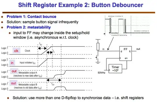
The switch needs to be debounced, which adds components to the circuit. And that's affected by your switch, whether it's SPST or SPDT.

You don't state the supply voltages or what kind of output your need from the switch. But as you mention a PROM, I'll assume you're looking for logic levels.

If you have a SPDT switch, it's somewhat easier...

schematic

simulate this circuit – Schematic created using CircuitLab

U1a debounces the switch and U1b provides your toggle function. R3/C1 deliver a reset pulse to U1b so its output is logic low after power-up. D1 discharges C1 into the Vdd rail when the power's switched off. (U1b's CLR pin has a similar input diode but not as strong as D1.)

If you have to use a SPDT switch, you need a different debounce circuit...

schematic

simulate this circuit

Here, monostable U2 is triggered by your switch being pressed and by all of its contact bounces. The re-triggered monostable doesn't expire for 11 ms, well after your switch contacts have stopped bouncing on closure. So the 555 outputs a single pulse high of slightly varying pulse width. This clocks U1a and causes it to invert, as before.

If you use the SPST circuit, you can use 556 dual timers and get two switch circuits for the two ICs needed.

TonyM
  • 21,742
  • 4
  • 39
  • 62
  • Nice answer but, you can debounce the switch with a simple RC circuit. It's easier and cheaper ;) – M.Ferru May 20 '17 at 19:44
  • Hi @m.ferru, thanks and you certainly can, I've done that before too :-) But you won't get a sharp rising edge from it to clock a DFF reliably so it needs to go through a Schmitt inverter. The RC needs a very slow rise time so it's not reached the Schmitt trip before, say, 10 ms bounce is over. It's a little more than just the RC. The 555/556 is also one IC like the 74HCT14 they'll need. Either way illustrates ideas to the OP so they can take the elements they need. – TonyM May 20 '17 at 21:17
  • It is possible to sharp the the signal coming out of the RC with couple transistors. It is finally get complexer than the 555 ^^'. At first view, I thought that the 555 was a bit "overkilling" for a debounce circuit – M.Ferru May 20 '17 at 21:27
  • @M.Ferru, I completely agree with your outlook. Knowing more about the OP's existing circuit would lead to something slimmer and I'm not a 555 fan. But it does show a solution to the OP, along with explanations of what, why and pitfalls. Thanks again. – TonyM May 20 '17 at 21:49