0

I'm trying to implement og test the results discussed in the linked JeeLab post in a low power battery powered device. http://jeelabs.org/2013/05/18/zero-power-measurement-part-2/#comments

The post describes a method for monitoring the battery voltage through a voltage divider that can be switched off by a P-channel and a N-channel mosfet. Similar solutions are discussed here:

Low Current Battery Monitor Detail Question

Low current battery monitoring

The question is how do I select an optimal N-channel og P-channel mosfet for this application? Which electrical parameters should I base the component selection on? If anyone have experiance with this method and/or selection of components sharing would be appreciated.
Peter Savnik
  • 125
  • 6
  • Make sure you do your math on the switching current on these methods. If you are sampling the battery voltage too often the current consumed in the measurement can quickly outweigh the benefits of the switch-off. – Trevor_G May 18 '17 at 14:37

2 Answers2

0

Check reverse leakage in datasheet. I would not use a mosfet for "true zero" power devices, but a NPN (PNP) bjt, with the same base capacitor trick.

A zero base current (or under Vbe) will easily ensure some nA collector current. This kind of devices you can see in car remote controls, where a NPN is connected directly to battery, while applying (OOK) modulation to base.

Use LtSpice to simulate.

See this Low Drain-Source MOSFET Leakage

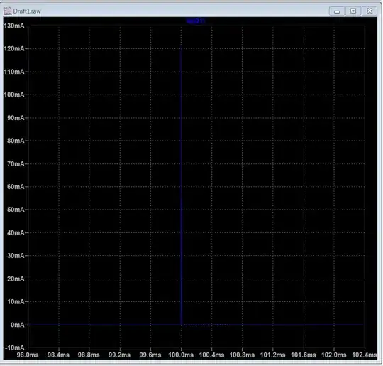
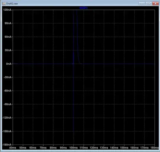
SIMULATED

enter image description here enter image description here

yo3hcv
  • 553
  • 1
  • 4
  • 18
  • Is the reverse leakage current the same as continious drain current? Why is your proposed solution more efficient? – Peter Savnik May 18 '17 at 12:51
  • See edited, but I strongly suggest you to simulate your device. – yo3hcv May 18 '17 at 13:03
  • Regarding the loaw drain-Source MOSFET leakage discussion: The voltage divider will draw a few micro amps. Most transistors i find eg. at Farnell's webshop are in the 10-500 mili amp area. I'm interested in, when powering off the device getting down to nano amps as you mention. – Peter Savnik May 18 '17 at 13:31
  • See edited again. – yo3hcv May 18 '17 at 13:48
  • Icbo = 10-15nA of typical 1 cent BJT's but Vce(sat) is a little higher even under Ic=1mA in 70mV range. You can Icbo under 1nA but pay in some other aspect or you can choose nom Icbo BJT from Diodes Inc and pay 10 cents to get <50mV For Vce(sat). This may not matter to you however. until you define your accuracy specs. – Tony Stewart EE75 May 18 '17 at 18:40
0

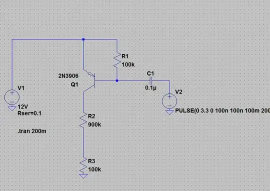
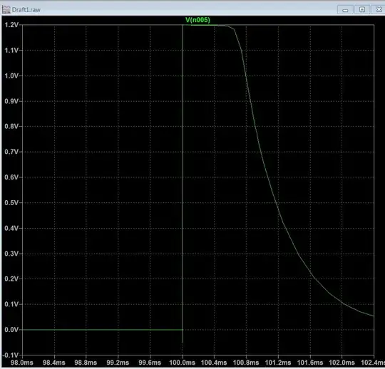
I don't know why I can't upload all images in single post. As you can see, the idle current is in some nA range. The divider is some trade-off between switch time and drawn current.

This is just a quick simulation, toggling with a 3V3 pulse of 100mS from some MCU. Adjust values that suits best for you.

enter image description here enter image description here

yo3hcv
  • 553
  • 1
  • 4
  • 18