I am making a LiFePo4/supercapacitor-hybrid.
Spike current draw can reach 300A for a few seconds. The LiFePo4 batteries I am using is rated for 100A max discharge rate. In order to make sure the supercapacitors do the heavy lifting, I need to limit the max current allowed to be drawn from the LiFePo4's.
In my circuit, the polyswitch will "switch off" in milliseconds at that kind of current draw. The power resistor will allow the supercapacitor to be recharged slowly while the polyswitch cools down. An obvious problem here is a waste of energy.
Is my idea completely senseless, or could it work?
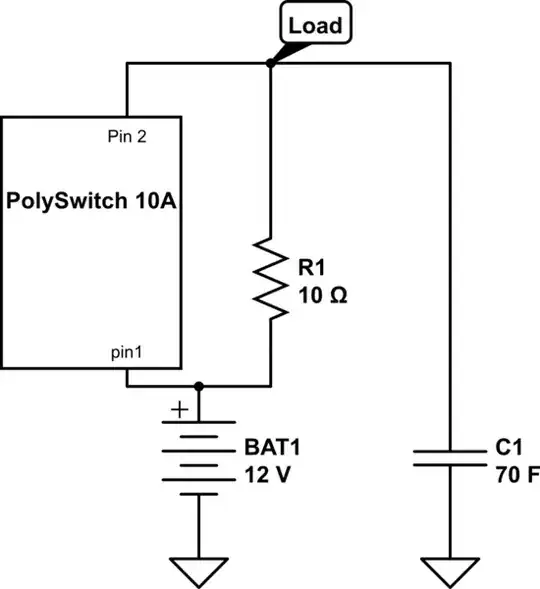
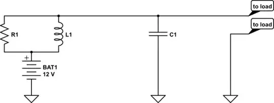
simulate this circuit – Schematic created using CircuitLab