3

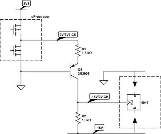
I need to connect two circuits that use different PSU voltages. The first is a microcontroller clock generator, it outputs a clock 0V to 3.3V at 150KHz as maximum freq. I need to connect this clock to a CD4047 (pin.3) on the second circuit. But the second circuit uses negative supply voltage and I cannot change that. So the CD4047 is powered with -15V and 0V. Obviously it won't accept my clock as is. I think I need a level shifter that converts the positive level of the clock to -15V or lower (I don't mind about the phase of the clock).

I tried the circuit shown in Figure 2 here: https://www.maximintegrated.com/en/app-notes/index.mvp/id/4414 I used a LM393 instead of the comparator used in that schematic, and powered it with 0V on pin 8 and -15V on pin 4 But it didn't work, maybe I got something wrong

Do you have any example tha I could use, or a different approach to do this task? Thank you

Dimitri Petrucci
  • 431
  • 6
  • 17
  • High speed opto-coupler? – JIm Dearden May 14 '17 at 12:09
  • a simpler solution for 3.3V square wave clock is AC couple with a very small current limited 100~1000pF cap to ANY logic inverter gate with 1M to 10M feedback R using of course using a spare gate using Vss=-15V and Vdd=0V to get a 15V square wave out. – Tony Stewart EE75 May 16 '17 at 00:08

2 Answers2

6

I'd rather go with a simple common base level shifter

schematic

simulate this circuit – Schematic created using CircuitLab

R1 is choosen not to saturate Q1 looking for "high speed" turn-off. In this conditions fall time is mostly ruled by R2 and output stray capacitance.

Output clock more probably swings from 0V to around 13V w.r.t the -15V line. This should be more than adeguate to 4047 input.

carloc
  • 3,174
  • 1
  • 16
  • 18
1

The problem with your circuit is that you are applying voltages to the LM393's inputs that are higher than it's positive supply voltage. This violates the input common-mode range spec (found in section 6.5 of the TI datasheet).

Carloc's answer is probably what I would do if I was solving this from scratch. But since you presumably have some LM393's on hand, you could also try this:

First get a new LM393 because you may have blown up the first one. Then try powering your LM393 with +3.3 and -15V instead of 0 and -15 V, so the input voltage won't be outside the power rails.

Because the allowed input common-mode range goes only to Vcc-1.5 V, you'll need to use a voltage divider to scale your 3.3 V high level down to, say, 1.6 V. And of course set the reference voltage on the other comparator input to about half of that (0.8 V).

Notice that LM393 has an open collector output (different from the MAX913) so you'll need a pull-up resistor on the output. This is a good thing for you because it means you can pull up the output to whatever voltage you like (0 V) and the output high level will be at that voltage instead of the positive rail voltage (Now +3.3 V).

The Photon
  • 126,425
  • 3
  • 159
  • 304