You can base your design in this question and its answers. In short, replace the resistor R22 by two resistors of equal value 1K, one of them connected to 0v, the other one connected to 20v.
(if, in other circuit elements you need also the virtual ground, this reference explains several methods to create one).
The circuit is:
simulate this circuit – Schematic created using CircuitLab
Analysis:
\$V_o\$ will we a rectangular wave (ideal op amp), with low level 0v and high level \$V_{cc}\$ . If we analyze the voltage at \$V_+\$ we have:
simulate this circuit
that means:
$$
0 = \frac{V_{cc}-V_+}{R_4}+\frac{V_o-V_+}{R_2}+\frac{0-V_+}{R_3} = \\
V_{cc}/R_4+V_o/R_2-V_+(1/R_2+1/R_3+1/R_4)
$$
Let \$V_H\$ the value of \$V_+\$ when \$V_o\$ is at its high level \$V_{cc}\$. Define \$V_L\$ the value of \$V_+\$ when \$V_o\$ is at its low level 0v:
$$
V_H = V_{cc} ~ \frac{1/R_2+1/R_4}{1/R_2+1/R_3+1/R_4}\\
V_L = V_{cc} ~ \frac{1/R_4}{1/R_2+1/R_3+1/R_4}
$$
Now, the analysis of \$V_-\$.
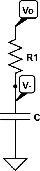
simulate this circuit
When \$V_{cc}\$ jumps from low to high, \$V_-\$ goes from \$V_L\$ to \$V_H\$, charging C across \$R_1\$ from \$V_o=V_{cc}\$ and reaching the high level in a time \$T_H\$; when \$V_{cc}\$ is at low level, it goes from \$V_H\$ to \$V_L\$. The equations are (see at end of this explanation for the demonstration of the exponential).
$$
V_-(t) ~ = ~ (V_{cc}-V_L)~(1~ -~ e^{- t / R_1 C})+V_L \\
\frac{V_H-V_L}{V_{cc}-V_L} = 1 - e^{ - T_H / R_1 C}
$$
thus
$$
T_H = - R_1 ~ C ~ ln \frac{V_{cc}-V_H}{V_{cc}-V_L} = \\
R_1 ~ C ~ ln (1+R_3/R_2)
$$
When \$V_{cc}\$ jumps from high to low, \$V_-\$ goes from \$V_H\$ to \$V_L\$, discharging C across \$R_1\$ and reaching low level in a time \$T_L\$ given by:
$$
V_{-}(t) ~ = ~ (0-V_H) ~ (1 ~ - ~ e^{ - t / R_1 C } ) + V_H \\
\frac{V_L}{V_H} = e^{- T_L / R_1 C}
$$
thus
$$
T_L = - R_1 ~ C ~ ln \frac{V_L}{V_H} = \\
R_1 ~ C ~ ln (1+R_4/R_2)
$$
note that \$T_H\$ and \$T_L\$ are controlled mainly by \$R_4\$ and \$R_3\$. Selecting appropiate values, or using a variable resistor to replace \$R_4\$ and \$R_3\$, it is possible to create a PWM (pulse wave modulator).
In an usual case \$R_2\$=\$R_3\$=\$R_4\$, the period of the wave will be:
$$
T = T_H + T_L= 2 ~ R_1 ~ C ~ ln 2 = 1.39 ~ R_1 ~ C \\
f = 0.72 / { ( R_1 ~ C ) }
$$
Addendum, demonstration of exponential equations used in this answer, based on Laplace transform:
In the charging stage, \$V_o(t)=V_{cc} ~ u(t)\$:
$$
V_-(s) ~ = ~ V_o(s) ~ \frac{1/R}{1/R+Cs} ~ = ~ \frac{V_{cc}}{s(1+RCs)} \\
V_-(t) ~ = ~ (V_{cc}-V_L)~(1~ -~ e^{-t/RC})+V_L
$$
In the discharging stage, \$V_o(t)=V_{cc} ~ (1-u(t))\$.
