0

I set up what I believe to be a working royer converter, however I did modify it to use a pair of op amps rather than transistors (see below.)

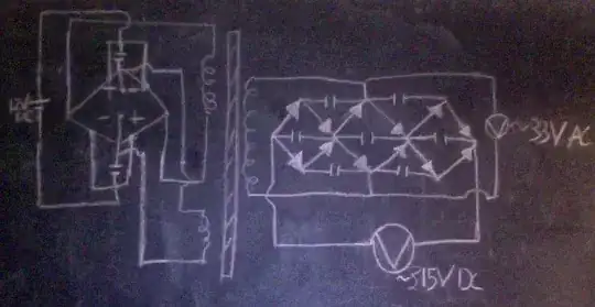
Anyway, instead of hooking the secondary to an lc tank, I hooked it up to a 3 stage full wave Cockcroft–Walton generator. My reasoning was that it would oscillate at a very high frequency and maximize power transfer as best it could.

I measured the ac voltage going into the CW generator to be ~33 volts. The dc voltage coming out was ~315 volts.

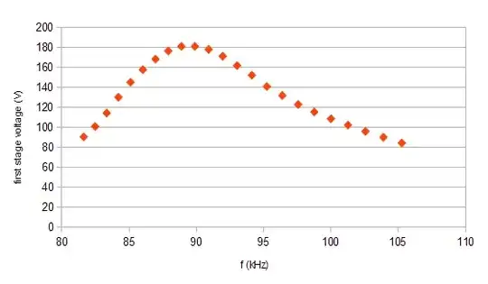
I suspect the CW generator to be exhibiting some kind of resonant rise, but I would be very interested to here a more thorough explanation from someone more knowledgeable. I know diodes can act as varicaps, transformers can act as inductors, capacitors have stray inductance, and op amps have built in capacitors, and there are two small capacitors being used to start the oscillation. So what components would have the greatest contribution to this resonance effect given that no inductors were explicitly used?

Below is a circuit diagram. The diamond shaped object is supposed to be two op amps back to back with their inputs crossed as seen here. circuit diagram

Alex Eftimiades
  • 831
  • 1
  • 11
  • 25
  • First, what is the problem here? You haven't said what is not working according to expectations. As far as we can tell, everything is working fine. Second, show a schematic. Just because you don't know how to draw it with one specific piece of software is no excuse. Draw it *neatly* on paper *with component designators* and scan it if you have to. There is always a way. – Olin Lathrop Apr 22 '12 at 14:06
  • Yes it is working fine, but I do not fully understand why. I suspect this is resonant rise, but I wanted to better understand what were the dominant components contributing to the resonance. I am working on a drawing on a blackboard. – Alex Eftimiades Apr 22 '12 at 14:34

2 Answers2

0

That's a rather unusual Cockroft-Walton design. All the ones I have seen are a single ladder with capacitors on the outside and diodes in the middle. This design with the triple capacitor strings maybe has more current capability. I'll have to think about this some more.

In any case, it looks like maybe this should multiply by 4. I've got things to do, and that's just after a quick look, not a careful analisys of this unusual design. The input is 33 V, presumably RMS. That makes it 47 V peak, and 93 V peak to peak it it's a sine. That times 4 is 373 V. You are getting about 84% of that. That sounds a little low for no load, so I'm guessing what is coming out of the transformer isn't really a sine wave so that the peak to peak voltage is lower than twice the square root of 2 times the RMS voltage.

In any case, it all looks like it's working at first glance. I don't see how resonance has anything to do with this since you are outright measuring the AC going into the CW generator. If you know what it is, it doesn't matter how it got there. You should look at it on a scope though to see what the actual p-p voltage is, since this is what a CW generator works on.

Olin Lathrop
  • 310,974
  • 36
  • 428
  • 915
0

I don't know what you mean by "resonant rise," but I don't think there is any resonant-type amplification going on here. The transformer will step up the signal from the oscillator, driving the RLC circuit formed by the transformer and the CW. At the right frequency, the reactances of the L and C will cancel, producing the largest voltage amplitude to drive the chain. Sweeping the frequency will let you map out the response curve, and there should be a resonance peak like the following.

Resonant peak of a transformer-driven CW

As Olin says, you have an unusual topology. I have seen CWs driven from both ends, but never from the middle. I suppose it works, though, and also reduces losses associated with driving multiple stages. You have a 3-stage full-wave CW, and each stage will see the full peak to peak voltage, ~93V, giving a total of ~280 volts. The numbers don't match up as close as I'd like, but I don't know your measurement setup, etc.

So you want to figure out exactly where the L and the C come from. First consider the CW chain, which has capacitors and diodes (with junction capacitance). The series combination is much more consequential than the parallel, overall, so the equivalent capacitance is on the order of the diode capacitance or smaller. When you translate it to the primary side of the transformer, it will be reduced further, by the square of the transformer ratio. The L is simply the transformer inductance.

In my experimentation with these kinds of CW circuits, I've found that it's convenient to set the resonant frequency by adding a capacitor across the primary. This capacitance then dominates the overall C.

mng
  • 1,330
  • 8
  • 9