1

I want to measure AC power of any general device such as TV, laptop etc using a microcontroller. My MCU is ARM Cortex-M TM4C1233H6PM.

I am using ACS712 current sensor to measure the AC current and then using an optocoupler to isolate it from my MCU. After which, it is fed to the ADC of my MCU and it's value measured.

My problem is with voltage measurement. I do not have access to many transducers and voltage measuring IC's in my area. Here is what I have though so far along with my questions related to it:

Use a transformer to convert from 0-220V AC to 0-5V DC and then feed it to my MCU's ADC using another optocoupler.But my questions are these:

1)Won't my voltage measured, be in a smaller range (0-5V DC) then my current measured in AC and the power will come out wrong? Also, since my voltage is now measured in DC, how can I calculate the AC power?

2)How can I find the zero crossings and phase difference (theta) to measure P=VIcos(Theta) in both current and voltage?

I know my questions may seem rather lengthy but I really do need your help. Thanks for any help!
Zero_Cool
  • 39
  • 2
  • Do you need to measure the instantaneous power use in less than 1/50 (or 1/60) of a second? Or would you contend with the continuous power usage over, say, one tenth of a second? In other words, is the AC and the zero crossings something that you actually need to cope with? – Dampmaskin May 09 '17 at 17:56
  • 1
    A transformer by itself won't make DC. Scale the AC down to 5V peak to peak (transformer,) add 2.5 V to that, sample with your ADC. In the processor, multiply AC voltage by the appropriate factor to get the true AC voltage. – JRE May 09 '17 at 19:06

3 Answers3

1

If you want to measure appliance power you need to digitise signals that represent alternating voltage and current waveforms. You should strongly consider simultaneous digital sampling of both quantities at a sampling rate of at least 1000 times per second in order to achieve some measure of accuracy. Multiply each simultaneous pair together and average the resulting waveform to give you power.

Using a dc quantity to represent voltage should not be regarded as having any merit. Trying to calculate RMS values for voltage and current then trying to measure phase difference by zero crossing is naive given the harmonic nature of current waveforms in a lot of appliances. This is not how pros measure power.

Power = voltage x current whether it's dc or ac, analogue or digitally sampled.

Andy aka
  • 434,556
  • 28
  • 351
  • 777
  • I get your point. So, basically, if my sampling frequency is many times the frequency of my AC mains, I will still get a pretty good approximation of power even without measuring P=VIcos(Theta) I have to generate a timer in my Code for that purpose to read input alternatively and then calculate power and store it so we can integrate it later. Is that correct? – Zero_Cool May 10 '17 at 01:35
  • Measuring VIcos(theta) almost always produces big errors because the harmonic content of the current waveform is usually quite bad on household appliances. You must read both inputs simultaneously not sequentially. If you only have one ADC and a multiplexer then get another ADC. – Andy aka May 10 '17 at 07:57
  • See this and note my answer: https://electronics.stackexchange.com/questions/82188/how-is-the-power-factor-part-involved-in-wattmeter-reading and this: https://electronics.stackexchange.com/questions/117392/using-the-raspberry-pi-to-measure-multiple-electrical-circuits and this: https://electronics.stackexchange.com/questions/76213/how-to-sense-the-zero-crossing-of-current – Andy aka May 10 '17 at 10:38
  • Also this: https://electronics.stackexchange.com/questions/202667/whats-the-most-economical-way-to-digitally-measure-240v-mains-voltage-current – Andy aka May 10 '17 at 10:41
1

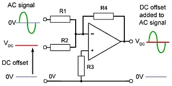
filo's anwser wont work if your ADC can't measure negative voltages. You could use a transformer or voltage divider, then use an opamp to add a DC value.enter image description here

In order to calculate AC power you just need to find a factor (constant) so you wont have trouble.

To find zero crossings you can use thresholds.

0

A transformer does not convert AC to DC (rectifier does that). Use a transformer to lower 230 VAC -> 5 VAC. Add a voltage divider (eg. 47k + 47k) across the secondary winding of the transformer. Connect one end of the divider to MCU ground and the center of the divider to your ADC pin (your MCU probably can measure only up to 3,3V). In this combination you will see your 230VAC as 2,5VAC referenced to MCU ground. You can measure that easily with ADC. When you are using a transformer you don't need another optocoupler.

schematic

simulate this circuit – Schematic created using CircuitLab

Keep in mind that most optocouplers are non-linear, so if you want to measure voltage coming out from your current sensor you have to pick a linear optocoupler or map the characteristic and correct non-linearity in software.

Computing the exact power and power factor from voltage and current is yet another topic.

filo
  • 8,801
  • 1
  • 25
  • 46
  • Thanks for your answer. It really explained a lot. For exact power, will it be okay if instead of measuring power factor, I increased my frequency(to calculate V&I) many times to that of AC mains or would that still give the wrong answer due to phase difference? – Zero_Cool May 10 '17 at 01:50