I am not able to understand what a load resistor is and how does it relate with a load.
Can anyone explain how the load resistor works and how is it different from the general resistor.
I am not able to understand what a load resistor is and how does it relate with a load.
Can anyone explain how the load resistor works and how is it different from the general resistor.
A load resistor is actually a bit of an abstract term...
If you consider an electrical circuit is intended to act upon some other device in order to perform "work" then that external device is the "LOAD" of the circuit.
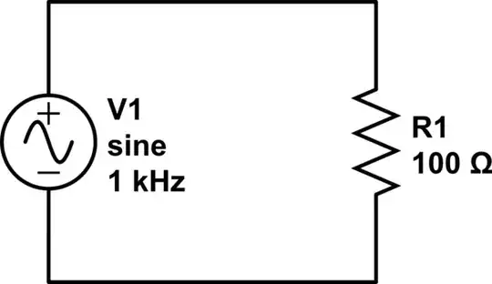
simulate this circuit – Schematic created using CircuitLab
However it is not that simple, since load must have a reference. Consider the circuit below.

Notice this time there is are two resistors \$R1\$, and \$R2\$. \$R2\$ is connected across the terminals of the left circuit that includes \$R1\$.
As before you can say \$R2\$ is the load for this circuit. However, you can also say the load across the voltage generator is \$R1 + R2\$. So you can see, they are strictly speaking BOTH loads depending on where you look.
However, generally speaking we say the thing that does the intended work of the circuit is the load.
Loads can be simple linear resistances or can be complex impedances as shown below.
As such load resistor can also have several meanings. The load on that circuit is the effective impedance of all those components on the right. \$R1\$ in this case can legitimately be called the "Load Resistor" since there is only one out there, but as you can see, that can cause confusion.
Just to make things more confusing, sometimes we use another meaning for load resistor.
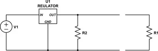
In the circuit above, the voltage regulator circuit is intended to drive the load resistor \$R1\$. However, because of the way this regulator works, it must have something attached to it to draw a minimum current in order for it to regulate properly. In order to comply with that requirement, an internal "load resistor" \$R2\$ is included.
In Summary
Load, and Load resistor in particular, is a vague concept intended to focus function on the objects in question and is always referenced back to something that is driving said load.
Load resistor in particular is heavily used during education to allow you to mathematically model circuits. Just like I have done above. In reality the load is seldom a resistor.
A 'load resistor' is simply a resistor that is being used as a load.
It may be very small, or may need to be physically big, depending on how much power it has to dissipate.
When you see descriptions of circuits, various resistors might be qualified by what they do, so you may see resistors called 'feedback', 'damping', 'source', 'bias', 'potential divider', 'isolating', they are all general resistors.
A load resistor is well... nothing but a resistor : a 2-terminal component that complies with Ohm's law and whose impedance is real (purely resistive, no reactance of admittance whatsoever).
What makes it a load resistor is the fact that it is placed at the output of something. The key here is understanding that, actually, a load resistor (or a resistive load) makes more sense as a modelling/analysis thing than as an actual thing. It's used, for example, to model the current draw you expect when you connect something to (i.e., when you "load") your circuit output.
Actual resistive loads are rarely called "load resistors". The widest used real-world mostly resistive loads are light bulbs, and nobody calls them "load resistors".
The generalization of this concept is the load impedance. A load impedance can be complex (not purely resistive, thus with reactance of admittance), so as to model the transient and/or frequency-dependent behaviour of something you connect to your circuit. Inductive loads are widely used to model motors, for example.
It's just a normal resistor.
It's called a load resistor because it is there to add a load to the circuit.
There is an implication that it will be dissipating a reasonable amount of power (otherwise it wouldn't be much of a load) but this isn't a requirement. e.g. early linear regulators required a minimum load to ensure voltage regulation, you would often add a small load resistor to ensure that this condition was always met.
A load resistor is simply a resistor being used as a load. It's not a special type of resistor. A load is anything that consumes power, whether it be a resistor, a capacitor, an inductor, or any combination of these three. A load resistor is supposed to be a pure resistive load that dissipates power as stated by Ohm's Law:

and

where P is the power dissipated, I is current, V is voltage, and R is the resistance in ohms. In the case of inductive and capacitive loads, replace R with impedance Z which is a combination of resistance and reactance.
In a circuit, an element which consumes electric power is considered as a load. Resistor also consumes power. So, resistor can be represented instead of load, or, every load is consuming power as the same way as resistor consumes. Example of load in electric circuits are appliances and lights. As the load can be any appliances, universally, it is represented as a resistive element.
A very short answer:
Each electrical/electronic circuit or device has a specific purpose: It shall deliver a signal or some kind of energy to a "consumer". Such a consumer will always draw some energy (current) out of the driving circuit/device. This current depends on the input resistance of the consumer. Hence, as seen from the driving circuitry: This input resistance of the consumer acts as a load resistance.