4

Trying to find if there is a suitable commonly available replacement transistor for a small circuit card on a Junghans W.707 clock movement (about 50 years old.)

Here's a picture of the whole thing http://www.hwynen.de/jgh-atomat.html (top right hand corner) and circuit cards shown below. Very simply, 2 coils, a capacitor and a transistor.

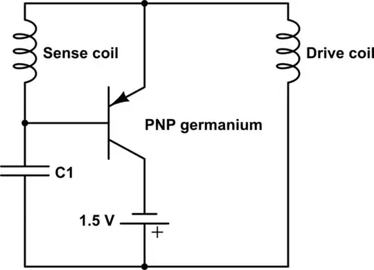
I then believe I've found a schematic of the card - http://www.bmumford.com/tmp/ATOschematic.gif however the actual circuit I have differs slightly from this layout but still only the 4 parts (2 coils, capacitor, transistor).

I have a similar clock with the same shape circuit card that I have swapped into the non-working unit and it works fine. The two interwoven coils, sense and drive, work with the oscillating spring balance that has two plates (above and below) with two small permanent magnets.

I'm pretty sure the coils are OK (measured for continuity) and I have even swapped the capacitor over and that is not the problem, which leaves the transistor. There are no markings on it to say what it is.

It is 8mm round by 7mm high; internal parts embeded in light green epoxy with 3 gold legs protruding and a small tag adjacent to one leg.

The working card, which has slightly different circuitry layout again - but still drives the movement, has a tall thin transistor (4.6 x 10mm) that has '13X' and a small red dot on it.

The whole thing runs off a 1.5V C size battery.

Does anyone know of a suitable transistor that would perform the job? If the original is available, where could I get it in Australia?

I did find a DIY guitar pedal site that seems to have AC125 gemaniums but 4 different sorts - but I don't know which of them would be suitable.

(DIY Guitar Pedals has some germanium transistors for sale, but I'm not sure which would be suitable.)

Replacement does not necessarily have to be the AC125 germanium. I'm only basing that on the schematic I found. I just want something to perform the job and I don't have enough knowledge to figure out what's suitable.

If it would help I can photograph my actual circuit (both sides) and draw the schematic but not sure what the internals of the transistor would be.


Schematic from above link:

enter image description here

JRE
  • 67,678
  • 8
  • 104
  • 179
Ian Stuart
  • 49
  • 2
  • Please post a schematic, repair questions are also off topic – Voltage Spike May 09 '17 at 04:29
  • Was suggested that I post a schematic here - however that requires me to leave a link and until I get more of a reputation on here I can only post 2 which I already have. If someone can suggest how I can leave a schematic I'd be pleased to know. – Ian Stuart May 09 '17 at 05:41
  • Thanks Jonk. It's certainly not a pendulum clock. If you look at the first link with the picture that shows the W707 movement and refers to it at the ATO principal (not sure what ATO stands for) the original page is in German and opening it in google it is easily translated. Maybe remove the pendulum schematic as that will just confuse the issue. Thanks. Ian – Ian Stuart May 09 '17 at 06:54
  • I have also drawn a schematic of the circuit I have (from the W707 movement) - and have a pic ready to post but not sure how I can post it as I'm only allowed 2 links and used both already. – Ian Stuart May 09 '17 at 06:58
  • @IanStuart I'll add a +1 to give some points. Maybe it will help. – jonk May 09 '17 at 07:08
  • @Ian post the links in the comments and we can edit them in for you. – Tom Carpenter May 09 '17 at 07:15
  • Thanks Tom. Have loaded it to my Google drive. https://drive.google.com/open?id=0Bz9J_I6pZ05kUnNydXZlbERwOVpQTXFQUUJwVGcxNEhna213 If you can post it into the body that would be great. – Ian Stuart May 09 '17 at 07:33
  • Tom, if you could also add the following comments below my 'incomplete' schematic - Pls compare this to the one I found online (ATO clock). Not sure what the internals of the transistor are so have left the circle blank. As I said earlier there are absolutely no markings on the outside of this transistor however the tag (emitter?) is closest to the leg that attaches to the central connection (between the coils). Does anyone know - looking at the circuit - is there a suitable replacement/substitute given the voltage and the design. (comments about design in first link) Thanks again. Ian – Ian Stuart May 09 '17 at 08:30
  • It seems reasonably likely that a silicon PNP could be made to work. – Russell McMahon Mar 18 '21 at 06:57

1 Answers1

3

You say to have found the AC125 transistor, but you don't know which to buy from the four offered. Probably they come in the flavours of different amplification factor. I would take the most expensive type, with the highest hfe (amplification factor), and lowest leakage. But for this simple purpose probably all four will work, but higher leakage could drain the battery quicker.

Use this one:

http://www.diyguitarpedals.com.au/shop/index.php?main_page=product_info&cPath=3&products_id=4

but I must say that $ 6.00 is not cheap. An American replacement for the (European) AC125 could be 2N1176 or 2N406 (even same pin-outs), but I think, for the simple purpose it is used, any transistor that is a low power germanium PNP will do.

I saw one photo from an ATO-mat print board, and I could only just figure out that the first character of the transistor type is definitely an A, so the chance that it really is an AC125 is there. I myself have a Junghans W.707 clock, but in there there's a much larger transistor used with no print on it. So maybe that they've used any (low power PNP germanium) transistor cheap in the market on that moment.

Here I found, and re-drawed another (slightly different) diagram. It could be that this is another model from Junghans: http://www.hwynen.de/jgh-w794.html

schematic

simulate this circuit – Schematic created using CircuitLab

Finally, you have measured the coils, and found them not broken, but see that there is a small possibility that two windings are shorted, and that is much more difficult to determine.