I am creating a circuit for an automotive application which will take 3 buttons from the stalk as 3 inputs. Now I have measured these buttons and they are active low and output a constant 12v (ish) when not pressed.
I am using an STM32F4 MCU to read the button presses and I realise that I need to drop the voltage of the buttons to 5V max prior to the digital IO pins of the MCU. After looking online I came across the idea of using an opto-isolator and because of PCB constraints I wish to use one which comes ready made in a SOIC package with 3/4 channels.
Now I see there are many available and so far I have determined I will use a transistor based one as it is a good middle ground and I don't need to deal with fast switching.
But I am confused as to how to choose one exactly as there are so many available. My requirements are:
- relatively low cost (up to £2)
- SOIC package
- triple/quad channel
- suitable for automotive voltages, 12V (possibly fluctuating a bit)
I am considering using the Toshiba TLP290-4 opto-isolator, which has a min CTR of 50%.
So by following the advice here: https://electronics.stackexchange.com/a/43502/148565
And considering the schematic (Just the forward voltage scenario, if I am not mistaken, this opto-isolator can handle reverse also):
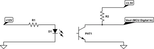
simulate this circuit – Schematic created using CircuitLab
I calculate that given a 10mA input current through R1 and D1, and the given 1.2V typical drop across D1 according to the datasheet, then R1 = VR1 / I = 1.08kΩ, so 1.2kΩ should do.
Then given the minimum CTR of 50%, at a 10mA input current, the output current would be 5mA. Therefore, assuming the 3.3V dropped across R2, R2 = VR2 / I = 330Ω.
So the question is, are my calculations correct and will the proposed circuit be safe for use under these conditions?
And as an aside, how would I go about inverting the output in terms of the switching, Do I just tie R2 to GND instead of 3.3V?