3

I have this setup where a PIR sensor (HC-SR501) powers an LED strip with the help of a P2N2222 transistor. enter image description here

I then manually connected the Transistor base to the 12v rail and it has no problem powering the LED strip. I have also tried changing the 2.2K ohm resistor with a 100 ohm and still the PIR sensor doesn't trigger the transistor. I have tried powering a 3.4V 8mm LED from the PIR sensors OUT pin and it works fine, so the sensor's OUT pin is giving the 3.3V. Is it not enough for the transistor base?

What am I doing wrong here? Please advice.

Thanks in advance

Kokachi
  • 668
  • 9
  • 23
  • 3
    You're trying to use the transistor as a high-side switch. If you want to use an NPN transistor, switch it on the low side instead. – Hearth May 08 '17 at 14:16
  • @Felthry ok, how do I do that? – Kokachi May 08 '17 at 14:18
  • Typing up an answer now, just a moment. – Hearth May 08 '17 at 14:19
  • 2
    We must have 100's of "transistor as a switch" questions like this with as many answers. Where's my dup-hammer ... ? – brhans May 08 '17 at 14:25
  • @brhans when interesting and or complex questions are put on hold minutes after they have been posted because "too broad" or "opinion based", that's what you are left with. I also like the "what resistor do I need for..." kind of question. They are very popular for the very same reason. – Sredni Vashtar May 08 '17 at 14:32
  • @SredniVashtar it may be vague for students , but pro designers know better to look for input specs and analyze load in this case a 500mA 12V stripled.. https://www.mpja.com/download/31227sc.pdf @ Kokachi next time make more effort to look at specs, schematic.. thanks – Tony Stewart EE75 May 08 '17 at 15:04

2 Answers2

5

Your problem is that the transistor is on the high side, and you're only giving it 3.3V on the base. Since your base-emitter junction must have approximately 600mV across it in order for current to flow from collector to emitter, your transistor is unable to have anything higher than 3.3V - 0.6V = 2.7V at the emitter, which isn't enough to turn on your LEDs.

schematic

simulate this circuit – Schematic created using CircuitLab

A better way to do it is as follows:

schematic

simulate this circuit

This way, the transistor has its emitter connected directly to ground, so the transistor can enter saturation when the signal is at its high level, and the transistor will have a low voltage drop (around a hundred millivolts) from collector to emitter. This means that you'll have almost 12V across your LED module, enough to power it.

Think of it this way: If, in the first schematic, your transistor was in saturation mode, you'd have approximately 0.1V between collector and emitter, and so the emitter voltage would be close to 12V, higher than 3.3V, and the base-emitter junction would be reverse-biased. Since a reverse-biased base-emitter junction means the transistor is not in saturation mode, this is a contradiction and the initial assumption (the transistor is in saturation) must be false.

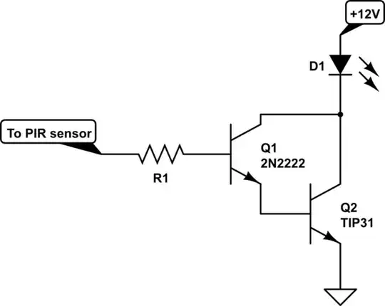
Now, up to this point, I've been assuming the transistor had a high β (aka hFE) at the operational current, which as Tony Stewart in the comments pointed out, is not correct. The 2N2222 is only going to have a β of around 30 or less at 500mA, meaning that it will be in forward-active mode and not saturation. Transistors in forward-active mode have a higher voltage drop between collector and emitter, meaning higher power losses, than when in saturation mode. Now, one obvious solution here is to increase β, which you can do like this:

schematic

simulate this circuit

This configuration is called a Darlington pair. Q2, here, is a TIP31 transistor rather than another 2N2222 for power-handling capability; Q2 is dissipating significantly more power than Q1, so it should ideally be a higher-rated transistor. Using a second 2N2222 may work, but a TIP31 is more suitable for the task.

Alternatively, you might want to look at Tony Stewart's answer below; his circuit is not quite so simple and requires the use of a MOSFET (which you mention having difficulty getting in small quantity), but has some marked advantages over the ones presented in this answer, such as lower power losses when presented with higher input voltages.

Hearth
  • 27,177
  • 3
  • 51
  • 115
  • will try it out and let you know the reult asap. thanks. – Kokachi May 08 '17 at 14:28
  • If the emitter of Q1 had 12V on it as in your first diagram, the LED would be lit! – Finbarr May 08 '17 at 14:31
  • @Finbarr hence my caveat of "if the transistor was conducting"! – Hearth May 08 '17 at 14:32
  • The base-emitter junction is not reverse biased as you state. The LED doesn't light because this circuit can only produce about 2.7V maximum across the load and that isn't enough. – Finbarr May 08 '17 at 14:36
  • I'll clarify. I meant to keep it fairly simple, but you're right, the way I worded it is misleading. – Hearth May 08 '17 at 14:39
  • @Felthry That did the trick, it works now. Problem solved. Thank you very much. – Kokachi May 08 '17 at 14:40
  • how hot is the transistor? what V+ did you use @ Kokachi?? @Felthry your answer ignored the PIR board specs and thermal rise of 500mA stripleds, if this was a design review (-2) tsk tsk ;) – Tony Stewart EE75 May 08 '17 at 14:46
  • @Finbarr I've edited the answer to be more in depth and less simplistic. – Hearth May 08 '17 at 14:49
  • @TonyStewart.EEsince'75 The question wasn't asking about that, so I didn't even look at the PIR board and explained why the transistor wasn't switching as the asker had expected. I've also never done much with PIR sensors, so I couldn't really have given good advice for that either. – Hearth May 08 '17 at 14:52
  • look deeper next time please. Remember this NO switch design can be done properly without input V and ESR compared with output ESR. BTW current gain of 10~20 for BJT's for conduction losses and switch "closure" is critical for Vce(sat) in this case Vce will be in linear mode, LEDs less than 500mA and T(BJT) very hot! – Tony Stewart EE75 May 08 '17 at 14:57
  • @TonyStewart.EEsince'75 I just tried with 2x 8mm leds isn series and the transistor is room temperature. Havent tried with the 12v 6W strip. – Kokachi May 08 '17 at 15:19
  • @Felthry Much better! :) – Finbarr May 08 '17 at 15:23
  • take my word of experience, 6W load or even 7W at 14V will be too hot – Tony Stewart EE75 May 08 '17 at 15:25
  • @TonyStewart.EEsince'75 Ooh, you're right. I forgot about derating β for large currents. I was running on the assumption of large β, but it would be significantly less in this circuit. Probably a good idea to use a higher-power transistor, maybe even a 2N2222 and a TIP31 in darlington configuration to limit the current draw from the PIR sensor. – Hearth May 08 '17 at 16:28
  • correct, so change answer or read mine. These stripleds are usually rated for cars @14.2V So dropping 1.2V with a Darlington from 12V is a dimmer solution. – Tony Stewart EE75 May 08 '17 at 18:45
1

If you examine the HC-SR501 schematic, datasheet, you will notice it says 3.3V TTL compatible logic level output yet adds 1K series R (for ESD protection), thus not True TTL output impedance with positive logic 1= detected human. So these two criteria , you must use an inverting FET switch with low side switching (-) to make it non-inverting , i.e. LED on with input high.

Question is how low does RdsOn need to be assuming Vth<=1.5V? 10Ω 1Ω 0.1Ω ?

I know that your LEDs 3V@500mA=1.5W has an equivalent ESR of ~1/1.5W=0.6 Ω x3 = 2Ω and series R's on ledstrips must be approx (14V-3*3V)/500mA= 10 Ω approx. total. and 2.5W =Pd total wasted for 7W applied with automotive range supply 12~14.2V possible.

We consider for thermal reasons, switch RdsOn about <=5% of load or Pd of 1/4W for this type, thus you can see with 1k series to an emitter follower 3.3V will never work to a 10 Ohm load even if it were 12V+1k logic and an hFE of 100. (DFM rules)

Thus 5% of 10.6Ω ESR load of Stripleds is 50mΩ which is the range more or less I would choose for your Nch enh MOSFET switching Drain to LED - and LED + to V+ which is from 12 to 14.2V

Final answer

schematic

simulate this circuit – Schematic created using CircuitLab

enter image description here

Tony Stewart EE75
  • 1
  • 3
  • 54
  • 182
  • isn't 3.3v too low for the gate of an N channel mosfet? – Kokachi May 08 '17 at 14:52
  • historically FET's Vgs= Vth were 4V then 3 then 1.5 now 0.7 and called Logic level power switches. Thanks to enhancemode technology and w/l ratios of junction – Tony Stewart EE75 May 08 '17 at 14:54
  • I can't get logic level mosfets here. I will have to bulk order atleast 1,000 or more. – Kokachi May 08 '17 at 14:57
  • no way.. anyone can order 1 from Digikey, mouser, RS, ebay etc and have it delivered anywhere within reach. – Tony Stewart EE75 May 08 '17 at 15:08
  • nope, I'm from India and our reserve bank has imposed very strict regulations on online purchase from outside the country. It's very very difficult to purchase from outside the country. – Kokachi May 08 '17 at 15:16
  • I was advised to use a transistor by another user in my [previous thread] (https://electronics.stackexchange.com/questions/303901/pir-sensor-led-strip-with-n-channel-mosftet) – Kokachi May 08 '17 at 15:37
  • @TonyM 's answer is ok using multiple BJT's with std N ch but this I think is simpler. whereas @p asserby neglected Ic/Ib ratio of 10 needed to prevent Vce(sat) rise in Tjcn which is impossible here. See for yourself and report back to him. – Tony Stewart EE75 May 08 '17 at 16:09
  • even worse that question shows 800mA load..This would never pass a design review using PN2222 with 1k on board from 3.3V to base – Tony Stewart EE75 May 08 '17 at 16:16
  • I reduced the load so that I could use a 2N2222 instead. Passerby suggested to use 2 of them transistors in parallel. – Kokachi May 08 '17 at 16:29
  • ok but that's not a solution if you have >=0.5A*Vce(sat) at Ib=(3.3-0.7)/1k=2.6mA max avail. and Vce becomes 1V if you had 10mA =Ib which you don't even if you had 10 PN2222A's see fig 4 of this NPN spec for Ic=500mA !! – Tony Stewart EE75 May 08 '17 at 16:45
  • well that IRL series mosfet you showed was from a seller in China and I couldn't pay because of restriction. All I have is 2N2222 and an IRF540N and an IRFZ44N. – Kokachi May 08 '17 at 17:34
  • hmm ok I see even listed in ebay.in I appreciate your feedback. – Tony Stewart EE75 May 08 '17 at 17:49
  • can the person who indicated -1 pls explain themselves? – Tony Stewart EE75 May 09 '17 at 00:27
  • @Kokachi I verified this works with either your FETs up to 5A and confirmed the others are far worse – Tony Stewart EE75 May 09 '17 at 02:59
  • Yes it is on ebay but the seller is from china and payment was in us dollar, so not possible. I do not know who gave you a -1 but now I have given you a +1. Thanks for the verified setup since I couldn't test it right away due to lack of 15k resistors. I presume the resistors are of 1/4W. :) – Kokachi May 09 '17 at 04:30
  • did you understand my solution? and why the 2N2222's will get hot? – Tony Stewart EE75 May 09 '17 at 14:51
  • Actually I understood why my 2n2222 _didn't_ get hot. My boost converter was only supplying maximum of 66mA at 12V. – Kokachi May 09 '17 at 17:00
  • I take that as NO, then I hope you understand square law.. \$P_D=I^2R_{CE}\$ – Tony Stewart EE75 May 09 '17 at 19:33