35

I need a way to invert a digital signal i.e. if the input is high, I want the output to be low and if the input is low I want the output to be high.

I think this can be accomplished with a single PNP transistor, but wanted to verify that here. The voltages that I'm dealing with are less than 5V.

Matt Ruwe
  • 1,957
  • 7
  • 23
  • 35
  • Detailed treatment of a BJT inverter: *[EE 307 Section 2 MoHAT Project](https://courseware.ee.calpoly.edu/~dbraun/courses/ee307/F03/13/02_13_PhilippeGonzaga.html)* - "The purpose of this page is to guide those interested in the fundamental operations of a BJT inverter." – Peter Mortensen Mar 30 '18 at 11:47

4 Answers4

40

Or, since you're talking about digital signals anyway you use an inverter.

enter image description here

A is the input (for gates with more inputs that will be A, B, C, etc.), Y is the output. If it doesn't complicate your schematic too much place the symbol with the input to the left.

Nexperia has single-gate inverters. Just four connections: power supply, ground, input and output.

It can be done with a transistor and two resistors, though. It's a simple schematic, but you still have to make a few simple calculations. You'll have exactly the same connections as with the inverter.
BTW, a PNP is an option, but more often an NPN will be used.

edit (re your comment)

enter image description here

If the input signal is high there will flow current through R2 and the transistor's base-emitter junction (base, not gate). This current will be amplified, and the collector current through R1 will cause a voltage drop so that the output will be low. Input high, output low.
If the input signal is low there won't be any base current, and no collector current. No current through R1 means no voltage drop, so that the output will be at +V. Input low, output high.

This already leads a bit further, but like I said in comment to sandun the output is highly asymmetrical. If the output is connected to a capacitor a high output level would mean that the capacitor is charged through R1, which will result in an exponential slope with a time constant R1C. When the output goes low the capacitor will be discharged through a much lower resistance and the slope will be much steeper. You won't get this difference with CMOS gates, which have symmetrical source/sink capabilities.

The transistor version's input will also draw (a small) current when high. The CMOS version will only have a small leakage current both when high and low.

Overall the integrated logic gate is the winner.

George Hawkins
  • 557
  • 5
  • 10
stevenvh
  • 145,145
  • 21
  • 455
  • 667
  • I certainly could be confused here, but an NPN turns on when power is supplied to the gate and a PNP turns off when power is supplied. It makes sense to use a NPN for signal amplification, but it wouldn't cause the signal to invert. Thoughts? – Matt Ruwe Apr 18 '12 at 17:47
  • 3
    Gates are for MOSFETs, not BJTs. NFETs turn on and PFETs turn off. But you must make sure the source is connected properly. An NPN and a PNP are BJTs and require some more math to make sure they work correctly – ajs410 Apr 18 '12 at 17:49
  • when it comes to the NXP you have very small room of freedom. There are constrains like timing, fan-in, fan out, input noise margins , glitches etc etc. In that case it's more than easy to use a transistor. Just because your not locked by those constrains. – Standard Sandun Apr 18 '12 at 17:50
  • @Matt - edited my answer. – stevenvh Apr 18 '12 at 17:54
  • 2
    @sandundhammika, If you build your own, you still have limits on fan-out and noise margin (fan-in doesn't apply here). But you have to calculate for yourself what those limits are. If you use the off-the-shelf gate you can just read the datasheet to find out. Furthermore, power consumption (another typical system constraint) is likely to be much better for the off-the-shelf gate. – The Photon Apr 18 '12 at 17:55
  • @sandun - the one transistor solution has a very asymmetrical source/sink profile, which may compromise rise and fall times. CMOS inverter outputs are symmetrical. – stevenvh Apr 18 '12 at 17:59
  • This is probably a stupid question and very basic (sorry for threadjack). I understand how the above circuit works.....but assuming Vs (the input) is set to high, which causes the Transistor to allow current from the Collector to the Emitter, how come current wouldn't ALSO go to Vo as well? I mean nothing is blocking it? Maybe I just don't understand voltage drop? –  Apr 18 '12 at 18:08
  • @Sauron - the collector current should be chosen such that Vo is zero. If +V = 5V and R1 = 1k then there can't flow more than 5mA. The resistor doesn't care if that goes to the transistor or the output. The current can't go higher than 5mA and the voltage drop can't go higher than 5V. – stevenvh Apr 18 '12 at 18:12
  • I think I understand what your saying, but if +V is 5v, and the NPN transistor is "Open" and allowing current going from Collector to Emittor, how come it isn't also flowing to Vo? (giving us a HIGH or one to the Vo output) –  Apr 18 '12 at 18:45
  • @Sauron - If there's current from collector to emitter there's a lot of it; we're driving the transistor in saturation, which means there's only a few hundreds of mV at the output. If the load is a 100\$\Omega\$ resistor, that will draw 200mV/100\$\Omega\$ = 2mA, but R1 can only supply the 5mA, so the transistor will only get 3mA. – stevenvh Apr 18 '12 at 18:51
  • +1 for the link to single-gate inverters. They and other single-gate logic elements sure save a lot of room compared to the old school (original 7400 and 4000 series) method of packaging several gates of the same type (6 in the case of 7404 hex inverter) into one IC whether you needed all of them or not in your circuit. Back then you often did need multiple gates of the same type, but now you often need just one gate here or there as glue logic. – tcrosley Apr 18 '12 at 21:43
  • @tcrosley, can you get single gate inverters in a package like TO-92? I'm breadboarding, and a surface-mount is not an option. My whole goal is to invert a serial output pin from an arduino to an older "LCD digital backpack" that wants inverted 5 volt serial data. A 14-pin package takes a lot of room on the small breadboard, and with tying all unused inputs to ground, a lot of fussy wiring as well. – Duncan C Jun 29 '14 at 13:41
  • @DuncanC Unfortunately you can't get single inverters in a through-hole package. However you can get two open-drain NAND gates in an 8-pin DIP -- [CD40107B](http://www.ti.com/lit/ds/symlink/cd40107b.pdf). You tie the inputs together to make an inverter. [Available here](http://www.digikey.com/product-search/en?pv1291=862&pv16=6547&FV=fff40027%2Cfff8019d%2C1140050&k=inverter&mnonly=0&newproducts=0&ColumnSort=0&page=1&stock=1&quantity=0&ptm=0&fid=0&pageSize=25). – tcrosley Jun 29 '14 at 16:53
  • @tcrosley, is the small 4-pin package I see in electronics catalogs a surface-mount package, or does it have pins that fit in a breadboard? – Duncan C Jun 29 '14 at 18:18
  • @Duncan Unfortunately, most likely surface mount. 4-pin single inverter is unusual, most are 5-pin SOT's or 6-pin. Unless it says DIP, it is surface mount. There are *very* few 4-pin DIP packages. – tcrosley Jun 29 '14 at 18:35
  • @tcrosley, 5 pin would be ok too. I'm just looking to avoid a big honking 14-pin DIP. – Duncan C Jun 29 '14 at 19:47
  • @DuncanC I wasn't very clear I guess; all the 4, 5, abd 6 pin devices are surface mount. A couple of messages back I gave you a link for a CD40107B in an 8-pin DIP with two NAND gates that can be wired as inverters (tie the two inputs together). I think that is the smallest you are going to find in through-hole. – tcrosley Jun 30 '14 at 00:29
  • @stevenvh If I understood it correctly, the Vo is the point where the actual output signal will be and it will be HIGH as long as there is no current through collector-to-emitter because the BJT's Gate (or base) is not ON. And the Vo which is basically a "Tap" if you will, will get all the current, but as soon as the BJT lets the current through it, the "Tap" will not get any current... is that correct? – fahadash Jan 14 '16 at 21:21
27

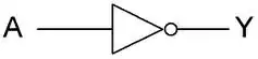
Yes, this can be accomplished with a single transistor and resistor, but there are chips specifically designed to invert digital signals. Oddly enough, they are called inverters. Check out the 74HC04, for example. That gives you six separate inverters in a single 14 pin package. There are also single inverters (and other small logic gates) available in small SOT-23 packages, which is the same package individual transistors come in.

There is little reason to try to make your own inverter, but yes, it is possible.

Added in response to comment:

As I said, a single bipolar transistor can be used as the basis for a simple inverter. At minimum, you need the transistor and a base resistor. For completeness I'll also add a output load resistor, which you should assume is needed unless you know whatever will be connected to the output will provide the necessary load. There is nothing magic about a PNP transistor in particular. A NPN can be used just as well. Here is how each would be used:

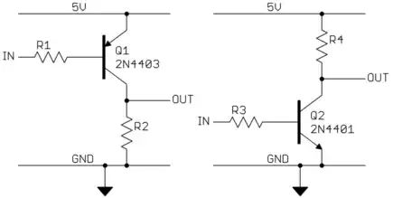
Note that each has 4 connections: power, ground, input, and output. The difference between the two is which direction it loads the input and which direction the output is actively driven versus passively pulled by the load. If you don't care about these issues, then the two circuits are functionally equivalent.

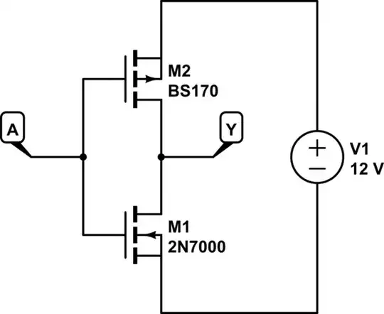
However, this is easier:

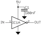
It's also faster, takes less steady state power, has higher imput impedance, and is smaller. It has the same four connections the inverters above do. Single gates like this are available in SOT-23 packages, which is the same package single transistors come in. This only requires one external part, the bypass cap. It doesn't need a load resistor since its output actively drives both ways.

Really, for general inverting of digital signals, making your own inverter is silly for normal applications.

Off topic aside about schematic drawing:

The script is really just three lines. Here is the whole file:

@echo off
rem
rem   MAKE_SCHEM_GIF
rem
rem   Creates a nicely filtered schematic GIF file from the raw Eagle output
rem   /temp/a.tif.  The resulting GIF file will be /temp/b.gif, and will be
rem   gray scale.
rem
image_filter /temp/a.tif /temp/b.img -shrink 5
image_copy /temp/b.img /temp/b.gif -form -gray
image_disp /temp/b.gif -zoom 1 -dev medium

It's a very specific one-off script, but works well enough for the purpose. In Eagle I export the schematic to image file \temp\a.tif, run the script which makes \temp\b.gif. The Eagle setting for image export are 600 DPI and monochrome. Really, that's all there is to it. It probably sound more complicated than it is.

Olin Lathrop
  • 310,974
  • 36
  • 428
  • 915
  • 1
    @MattRuwe it would "suffice" but Olin's point is that a dedicated chip would do better (the rise and fall time would be more symmetrical). A PNP can "pull up" to Vdd, but you need something to pull it back down when the PNP lets the output float. That "something" will create asymmetry in the rise/fall time, based on its impedance. – ajs410 Apr 18 '12 at 17:47
  • Gotcha, makes sense – Matt Ruwe Apr 18 '12 at 17:48
  • 1
    How come your schematic looks prettier than mine? :-) – stevenvh Apr 18 '12 at 18:13
  • 4
    @stevenvh: Must be because I'm just better. Seriously though, I use Eagle and take some care. After drawing in Eagle, I export the schematic at 600 DPI to a image file, then run a script that filters and shrinks it 5x and writes the result to a gray scale GIF file. That makes the result a reasonable size without pixel artifacts. It does make lines a little fuzzy though, which is the tradeoff for not having aliasing and visible pixellation. – Olin Lathrop Apr 18 '12 at 18:24
  • Huh, script for that? Did you code it yourself? Also, why do you never use "an" :) – abdullah kahraman Apr 18 '12 at 20:35
  • 1
    @abdullah: See addition to answer. – Olin Lathrop Apr 18 '12 at 20:57
  • What are `image_filter`, `image_copy` and `image_disp`? If they're programs I don't have them on my PC (XP). – Federico Russo Apr 26 '12 at 12:37
  • @Federico: Those are part of my suite of image manipulation programs. They should be included in my general software release at http://www.embedinc.com/pic/dload.htm – Olin Lathrop Apr 26 '12 at 13:44
  • Olin, thanks for an excellent answer. I am wiring a serial LCD display to an Arduino. (An older model "LCD Digital Backpack.") The LCD display wants inverted signals, and the Arduino does not put out inverted signals. I've built an inverter using a CMOS 4001 NOR, but that means tying up 15 pins on a small breadboard, plus tying all the unused inputs to ground so they don't float. I'm interested in using a transistor and a couple of resistors instead. How would I calculate the resistor values for a 5 volt 9600 baud signal? – Duncan C Jun 23 '14 at 21:55
  • @OlinLathrop, can you give an example of a component (with part number, so I can find it) in an SOT-23 package as you describe? It would be handy when all I need is a single inverter, and I don't want to take up all the space for a DIP 14 of inverts on my breadboard. – Duncan C Aug 19 '14 at 00:11
  • Can you explain the purpose of R2 and R4. I am trying to learn about electronics and I am unsure of the reason why to have those resistors. – Justin Jan 04 '16 at 17:38
  • @OlinLathrop What about cost? An inverter costs close to 10 cents at a quantity of 1000 whereas an MMBT2907 costs around 4 cents. I'm counting the passives as negligible. https://octopart.com/search?q=&=&start=0&specs2.2.values=SOT-23&specs2.2.values=SOT-23-8&specs2.2.values=SOT-23-6&avg_avail=(1__*)&category_ids=4274&specs2.144.values=Inverter – Anton Sep 29 '17 at 05:14
  • @Ant: At that level of details, the passives aren't negligible. You also have to consider the pick and place cost. Anyone that is designing products at the volume where $.10 versus $.04 matters should already know what they are doing and doesn't need to ask here. – Olin Lathrop Sep 29 '17 at 10:40
  • @OlinLathrop True. – Anton Sep 29 '17 at 16:55
  • What are `image_filter`, `image_copy`, and `image_disp`? Part of Eagle? Part of some Adobe package? [ImageMagick](http://en.wikipedia.org/wiki/ImageMagick)? Googling those 3 does not return anything interesting. Perhaps add a short note to the post about this? – Peter Mortensen Mar 25 '18 at 12:12
  • @Peter: Already answered, in comments. – Olin Lathrop Mar 25 '18 at 13:47
9

Here are some resistor values that work for CMOS signals:

I found this thread because I wanted to wire an older "LCD Digital Backpack" to an Arduino. The Arduino puts out positive serial signals, and the digital backpack wants inverted signals. Newer version of the LCD controller have an inverted/non-inverted jumper, but mine does not. Similarly, it's possible to generate inverted serial signals through software, but it involves running a non-standard library. I wanted to use the standard Serial.write commands.

I initially wired up one of the 4 NORs in a 4001 CMOS quad NOR gate as an inverter, but that takes up a lot of room on my breadboard, and since you're supposed to tie all unused inputs to ground, involves a lot of wiring. (I think I needed to connect all but 3 of the 14 pins on the package; everything but the outputs on the 3 unused NORs.)

I wanted a simpler-to-wire solution. I used the circuit provided by @stevenvh.

Linked here:

enter image description here

I'm dealing with 5V CMOS logic at 9600 baud, so the input impedance is very high/current is very low. Since I'm only switching at 9600 baud, I don't think the asymmetric behavior of the transistor based inverter hurts me much.

I found that a 100K resistor on the input (R2 in stevenvh's diagram) worked, and used a 3.3k resistor as the pull-up resistor at R1. Based on my calculations (I=V/R, 5/3300) this setup will draw <= 1.5 mA in the ON state (Somewhat less due to the internal resistance of the transistor.) I might hook up a pot and see how large a resistor I can get away with an still have the LCD receive a signal.

Duncan C
  • 1,398
  • 2
  • 15
  • 27
4

Here is how you do it the CMOS way:

schematic

simulate this circuit – Schematic created using CircuitLab

The power rail voltage can go as high as you like as long as it is lower than the gate breakdown voltage.

Maxthon Chan
  • 2,853
  • 1
  • 16
  • 33