0

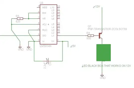
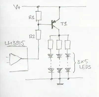
I am connecting the LM3915 to a PNP transistor to drive LEDs. I have it working in bar graph mode using one LED per output directly (no transistor).

On page 7 of the datasheet, it looks like pins 1,10-18 should put out a "0" when in the ON state. Connecting the PNP directly does not work. Measuring the output of the LM3915, I get about 4V, when OFF and 3V when ON. I'm measuring using both DVM and O-scope. I don't know how to drive the PNP with this output.

Qs:

1) Is my test result correct? If yes, where does it say this on datasheet? I see saturation voltage at 0.4V under output drivers (page 3, TI datasheet)

2) Page 3, electrical characteristics. What does Divider Resistance mean? I know what a voltage divider is, just what does it mean to do with this chip?

3) The threshold chart makes no sense to me. My range is 1.2V, I think (also don't know how to set this), but the threshold V chart (page 4) shows a range up to 10V.

Thanks

enter image description here

markrages
  • 19,905
  • 7
  • 59
  • 96
Tom
  • 1
  • 1
  • If you refer to the datasheet you could at least provide a link. – stevenvh Apr 17 '12 at 16:44
  • 1
    And a schematic would be nice. How did you connect the 3915 to the PNP? – stevenvh Apr 17 '12 at 16:45
  • I added your schematic. Notice that the base of PNP will be about 12-0.7, or 11.3 volts. The datasheet recommends VLED ≤ V+, although it is an open-collector output, so it's not clear what badness happens when VLED > V+. – markrages Apr 18 '12 at 00:16

2 Answers2

1

In this answer I explain how to drive a chain of LEDs from an LM3915, using PNP transistors. Is this what you want?

enter image description here

The divider is an internal resistor chain which creates the reference voltages for all comparators. Each of these comparators drives one output.

stevenvh
  • 145,145
  • 21
  • 455
  • 667
1

Tom, the LM3915 is a very efficient, effective, easy to use, simple log scale LED driver. Why do you want to add a bunch of PNP's with current limiting resitors and mess it up? Choose any color LED's you want with any brightness and viewing angle you want. Red/yellow tend are ~ 1.7V, Blue,green & white are ~ 3.2V diode drops so if using a 5V supply the open collector current source drivers will read 3.3V on red LEDs when on and then float up to 4V with just leakage current biasing the diode @ ~1.4V which is near the "knee" of the diode V-I curve.

I use > 10,000 mcd 30deg Red LED's @ 20mA so that would be 5 Cd @ 10mA, which is the recommended max for all outputs active to the chip. That should be blinding across the room. ;) Of course you can adjust the output currents with the Ref Current which is approx 10% of output.

Look at Page 7 schematic. of spec sheet. THe long string of resistors is a ladder of log-weighted values to give the logarithmic curve with all the comparitors to activate each LED.

Although you only need at least 2 R's to make a "divider" ( read .. voltage ratio from resistance ratio)

The input is driven to all differential comparitors and the maximum input threshold is set by the voltage R-hi on pin 6, which can be adjust on pins 7 and 8 just like a 3 terminal regulator ( read LM317 specs if a newb.)

Take note about using caps in notes to reduce false triggers from switching noise.

Actually this cct is much like our brain's analog computer in threshold decisions.

stevenvh
  • 145,145
  • 21
  • 455
  • 667
Tony Stewart EE75
  • 1
  • 3
  • 54
  • 182
  • I think he is trying to make it work with a commercial LED device that is intended to work from 12V. I don't know what else a "LED black box" could constitute. – Connor Wolf May 05 '12 at 08:21
  • Possibly the OPs ominous "LED black box" contains an array of LEDs with only one common cathode. This would prevent him from using the OC outputs directly. – Curd May 05 '12 at 08:41
  • 1
    OP's schematic is the best solution if the LEDs need more than 30mA. – Federico Russo May 05 '12 at 08:58