3

Just when you think you understand electricity, it throws another curve ball at you.

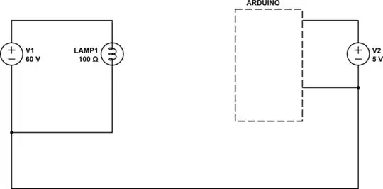
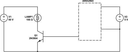
The following circuit confuses me. The Arduino has it's own power circuit supplied by either batteries or a transformer at +3V. The light bulb is powered somewhere between 0 and 60V by a separate circuit. Its ground, however, is connected to the Arduino's ground pin. To further confuse me, the gate is being driven by the Arduino, but its pulled down resistor is also tied to that ground.

enter image description here

I was under the impression that high powered circuits should be electrically isolated from the lower powered digital circuits. How can this work without destroying the Arduino? Why would you want to do this and where does the current sink to? The Arduino circuit or the external circuit?

user148298
  • 2,215
  • 5
  • 36
  • 51
  • 1
    Ow. That is asking for a dead Arduino and/or an injured user. Who drew that? Besides not being a good idea, the voltage markings are stupid. – JRE Apr 21 '17 at 17:09
  • I got it from this page: http://bildr.org/2012/03/rfp30n06le-arduino/ To be fair, there are numerous other resources recommending this wiring approach. Regardless, if it is indeed bad, how did they live to right about it or is this someone's way at lashing out at the world? – user148298 Apr 21 '17 at 17:14
  • I sure wouldn't do this. Maybe once, if I had a spare Uno laying around, just to see if it would work. But I get leery about having anything more than about 30 volts within easy reach. (Even the 49 volts on phone lines is enough to make me not want to touch it. And God forbid that the phone might ring at 109 volts.) My bottom line for this circuit is that I would use the Uno to drive a 5V relay and keep the circuits totally separate. – SDsolar Apr 21 '17 at 17:22

3 Answers3

8

Because of a basic rule of electricity, current only flows around circuit loops.

When you have two circuits, with no other connection between them, you can tie them together at ANY point to form a common reference voltage as shown below. No current will actually pass thought that connection without a second connection to complete a loop.

schematic

simulate this circuit – Schematic created using CircuitLab

Once you have created that common reference it is then possible to pass signal voltages between each side as shown here.

schematic

simulate this circuit

If you notice, the current driving the lamp only returns on the 60V side, while the base current returns on the Arduino side.

This is quite safe and normal.

The issue with mixing grounds occcurs when you pass the returning high current through the control sides low current circuits as shown below.

schematic

That creates noise and reference level changes on the control side which can cause unpredictable behaviour in the low voltage electronics.

The circuit in your image falls into the correct wiring category.

ADDITION FOR COMPLETENESS.

Note I said... "At any point". The following circuit is ALSO acceptable.

schematic

simulate this circuit

Trevor_G
  • 46,364
  • 8
  • 68
  • 151
  • I just realized that high school electronics isn't good enough to do even the most basic electronics even if you aced all the physics exams. It only serves to confuse and demoralize the victim. American schools suck! We always assumed there was one and only one power source because that's the only type of circuits we worked with. BTW, I couldn't simulate your circuit for some reason. Is it because the Arduino isn't defined. – user148298 Apr 21 '17 at 17:45
  • @user148298 yes that's just a drawing for you visual pleasure and understanding. And yes, high school electronics only takes you so far. I did not want to confuse you with my answer, but in the first circuit I drew it is also quite permissible to join the ground on the right to the +60V line. You would not be able to drive it like that though. – Trevor_G Apr 21 '17 at 17:47
  • @user148298 see my update to the answer. – Trevor_G Apr 21 '17 at 17:54
  • Sorry, but you can join the arduino ground to the 60+V? – user148298 Apr 21 '17 at 17:55
  • @user148298 as long as the power supplies are isolated you can join them anywhere you want and call that ground. Generally we don't do stuff like that because it confuses people, but it is quite doable if you keep track of what you are doing. – Trevor_G Apr 21 '17 at 17:56
  • Thanks for all your help. Can you recommend a good theory book on how electricity behaves that doesn't make you feel like an idiot by using mathematical formulas? Math definitely proves it, but doesn't explain it. – user148298 Apr 21 '17 at 18:02
  • 1
    @user148298 you are right math sometimes just confuses you, while a laymans description paints a picture. Unfortunately my knowledge of current books on the subject is pretty much none existent. My 40+ years experience working with it and explaining it to folks is all I have. Maybe I should write one.. LOL But don't be afraid to ask questions like this one on here. There are lots of folks that have that XP to help you. – Trevor_G Apr 21 '17 at 18:07
  • 2
    @user148298 I would recommend: Horowitz & Hill: The Art of Electronics, 3rd Edition. Go buy one now. (I have no affiliation with the authors). ISBN: 0521809266 – Chris Knudsen Apr 21 '17 at 19:23
  • 1
    @Trevor I would definitely write one. You certainly know your stuff and can explain it well. You should also explore other media as well such as video and or electronic books with graphical illustrations and animations. There's lots of online stuff out there, but it's all scattered information of varying quality. – user148298 Apr 21 '17 at 19:57
  • @ChrisKnudsen Thanks for the info. I will order it today. If you or anyone has other books, feel free to suggest them. Sometimes, getting several perspectives is better than one. – user148298 Apr 21 '17 at 19:59
  • @user148298 - "If you or anyone has other books, feel free to suggest them." FYI see the main "book recommendations" topic on EE.SE here: https://electronics.stackexchange.com/questions/616/basic-electronics-book – SamGibson Apr 21 '17 at 22:24
  • PS: you might want to introduce galvanic isolation such as optocoupler if you are afraid that there will be a fault in your high power system, so that it doesn't destroy the arduino when it happens. – Unknown123 Feb 21 '19 at 03:22
1

In general this should work without harming the Arduino. What matters is that both circuits use the same ground reference. They don't have to be fully isolated, but they do need to use the same ground. The reason for isolating circuits is to keep electrical noise in one from damaging or otherwise affecting the other. High "power" circuits (as opposed to high voltage) tend to have higher current, higher currents are subject to inductive noise spikes. A noise spike of 2-3V might not have any consequence to a 100V circuit, but that is enough to the change the input on an Arduino. A 10V spike, no matter how short can damage a 3.3V input.

MarkR
  • 21
  • 2
-1

First, high voltage circuits do not have to isolated from the low voltage one they can interact if designed well. However it is good practice to isolate high voltage circuits from low voltage circuits for the safety and shock prevention to users.

Two, there is not reason for this circuit to not work because the is not current from from the +60V rail to the arduino. I'm assuming that their notation implied as follows: 0-60V+ = Power Rail any where from 0 to 60V 0-60V- = Return for the 0-60V+

The current will flow from the +60V rail through the lamp from drain to source of the MOSFET to the return line. Remember that the gate is isolated from drain to source (as long as the MOSFET specs are not violated).

Then from the Arduino the gate of the MOSFET is driven since the output voltage of the arduino is reference to the arduinos ground and the MOSFET cares about the Voltage across the drain and source terminals, therefore the source of the MOSFET has to be referenced to the arduino's ground. In this path current will flow from the arduino pin, through the pull down back to the arduino's ground.

Kvegaoro
  • 3,141
  • 17
  • 14