1

I am designing an IR demodulator circuit to replace the one shown in this question. Basically I want to demodulate a simple IR signal modulated at 32.678 kHz. I just need to know if the signal is present. No packets. Just IR present or not present.

Below is what I have so far... IR Demodulator Virtual Ground

I have tried simulating this in LTspice with no success so I am not sure if I've done something very wrong in spice or in my circuit. I am no pro with LTspice.

R1 N001 N006 2.49K tol=1 pwr=0.1
R2 Output N003 1Meg
R3 N006 N005 1Meg
C1 N005 N004 470pF
C2 N003 N001 220pF
C3 Output N001 220pF
V1 N006 0 2.5
V2 N002 0 5
V3 N004 0 PULSE(0 .05 0 0 0 0.0000152587890625 0.000030517578125 200)
XU1 N005 N003 N002 0 Output LT1722
.tran 12ms
.lib LTC.lib
.backanno
.end

I have a few questions:

  1. How best do I determine the value for R34? I have left it at 22k simply because the previous circuit used this value.
  2. C16 and R31 set the high pass knee point. What would be a wise choice for this value?
  3. The overall gain of the circuit is approximately 400 by my calculations. So, in choosing my op amp I would need a GBWP of 14 MHz or greater? Any other critical op amp specifications for this application? Note the amp showed is just a place holder until I choose the op amp.
  4. If I wanted to increase my gain beyond what is shown (~1000) would it be best to break this up into several stages?
Jason
  • 1,923
  • 1
  • 20
  • 31
  • Do you need to keep that structure? Also, do you have access to +10V? Because the PNZ323B is specified for a reverse voltage of 10 V. – Telaclavo Apr 17 '12 at 09:44
  • 1
    The TLE2425 is way overkill for what you need it for. A resistor divider followed by any opamp buffer will do the same thing for a fraction of the cost. – stevenvh Apr 17 '12 at 11:18

5 Answers5

3

Answer rewritten due to new information from Jason:

Some other answers talk about using a custom IR received IC - which is what I would tend to do except where price was utterly crucial and I could make a cheaper design wit acceptable performance discreetly.

But, this answer is aimed at making the existing circuit work as it should, as requested.

MCP601 op amp datasheet here
This is single supply, rail to rail output, Vin = ground to Vdd-1.2V. So with Vdd = V5.0 = 5V Vin range = 0 - 3.8V.
Set ideally set mid point at about range/2 = 1.9V or so but 2.5V used is OK.

R31 to Vground = Vdd/2 provides DC level for opamp input and output. With no signal Vout = V5.0/2 = 2.5V so output of D5 will be about 2.7-Vd = 2.5-0.5 =! 2.2V. You ideally want Vout ~+ 0 at 0 input - see below.

Filter looks to have potential for massive gain at some frequency ( ~~R17/R18 = 400:1 as noted) - whether this occurs anywhere depends on overall filter action. I'd be more comfortable if the basis for the design was described.

C16/R31 provide a high pass at << 1 kHz so well below IR frequency.
You could increase this till it approaches IR frequency but far enough away for minimimal attenuatio bit that depends whether it was a formal part of your overall filter design - if it wasn't it should be. For best results te overall front end frequency response should be tailored to be a bandpass of designed characteristics.

Try this: _

Aim: AC couple op-amp output so
Vout = positive signal peaks from op amp - V_D5

  • Drive D5 with a capacitor = Cout = say 10 uF electrolytic so D5 is AC driven.

  • Add D6 to ground with D6 cathode to Anode (D5 input) and D6 anode grounded.

This causes positive half cycles to be passed through D5 and to charge C15 and negative half cycles to be conducted through D6 to ground.
This is potentially " a bit hard" on U1a and Cout = 1 uF may suffice.
Cout > C15, to Cout >> C15 is desirable to stop the two dividing the output positive peaks by too much.

enter image description here Report.

Russell McMahon
  • 147,325
  • 18
  • 210
  • 386
  • I derived it from a few text references I have. :) I just realized that I screwed up when drawing AND simulating the circuit. R17 is supposed to feed back to the inverting terminal which gives the DC path. I'll have to edit my question in the AM. – Jason Apr 17 '12 at 08:29
  • R31 keeps the opamp biased at VGND (2.5 V), not GND. So, no distortion from that. – Telaclavo Apr 17 '12 at 09:39
  • @Telaclavo - ah thanks - missed that. Writing too large for my brain :-). – Russell McMahon Apr 17 '12 at 10:57
  • And the cutoff frequency for the OP's C16/R31 is 331 Hz, not 2 kHz. That is too low. I would use C16=220 pF and R31=50 kohm, to have at least fc=10 kHz, and filter all the noise up to those freqs. – Telaclavo Apr 17 '12 at 11:05
  • @Telaclavo - brave the man who can locate a single RC pile to 1 Hz :-). But yes, a 2Pi in order. More or less. – Russell McMahon Apr 17 '12 at 11:15
  • I can. Just give me piles designed for fc=2 Hz. – Telaclavo Apr 17 '12 at 11:38
3

I agree with Tony, I would also use an integrated IR receiver. The only problem seemed to be the 32kHz, IR receiver modules are often narrow band around 38kHz to 56kHz. But when I checked my usual supplier Vishay they also seem to have non protocol specific modules covering 32kHz, like this one.

Main advantage of this kind of modules is that it does a lot more than your circuit:

enter image description here

The AGC (Automatic Gain Control) is important. It ensures that sensitivity is adjusted when a proper signal is received, so that noise (for example from HF fluorescent lighting ballasts) is suppressed.

stevenvh
  • 145,145
  • 21
  • 455
  • 667
  • +1 for that AGC idea.Please give some examples on configuration. Thx in advance. – Standard Sandun Apr 17 '12 at 09:56
  • @sandun - Do you want to know how to design an AGC? – stevenvh Apr 17 '12 at 10:16
  • it's complete offtopic. what about how to modify OP circuit to do that? – Standard Sandun Apr 17 '12 at 10:23
  • @sandun - Isn't that exactly the same question? – stevenvh Apr 17 '12 at 10:25
  • oky I think your right, I'll do some research first and then ask it n a new thread – Standard Sandun Apr 17 '12 at 10:30
  • Actually the AGC is a problem in this case. Look at the TSOP datasheet carefully and you'll see these modules aren't meant to receive a continuous signal. After a while, the AGC will tune it out as background. A module like this would be my first choice too if the IR carrier could be periodically interrupted, like 20 cycles on, 20 cycles off, etc. The module would then produce a square wave, which downstream circuitry would detect as presence of the IR beam. – Olin Lathrop Apr 17 '12 at 11:34
  • @Olin - Good point! That's also why receivers are developed for specific protocols, most of which indeed have these interruptions. (My experience is mostly with RC5, which has a pause of 50 bit times after each 14 bit command.) I don't know how the non protocol specific devices do it. – stevenvh Apr 17 '12 at 11:40
  • In the case of non protocol specific, they use a filter to detect the presence. And it's a simple PWM motor control unit with 555. But I'm pretty sure it doesn't contain a AGC. The IR input is directly connected to the 555 trigger pin. So even for such a analog application interference would not be a hurt in advance. – Standard Sandun Apr 17 '12 at 11:47
  • @sandun - The [TSMP4138](http://www.vishay.com/docs/82454/tsmp4138.pdf) I linked to does contain an AGC. – stevenvh Apr 17 '12 at 11:50
  • @OlinLathrop I'm not sure of what you say. It might be as you say, but I think that the datasheet does not state it, clearly (other than just saying "receiving the modulated signal"). So, if that was the case, shouldn't it specify the maximum on time for the pulses? Where is that parameter? Or, in other words, reversing the question: If you were to design an IC for what the OP needs, couldn't you take advantage of an AGC? I think I could. I believe that the AGC works at the 32 kHz level, not at the few hertzs or so of the data. Not sure, though. – Telaclavo Apr 17 '12 at 12:02
2

In addition to what others have said, I would point-out that your filter arrangement is suspicious. At first glance, the portion of the circuit from U1 pin 3 to U1 pin 1 looks like a typical second-order bandpass filter but instead of driving the left hand side of R18 and grounding the non-inverting input of U1, you are doing the opposite, ie using it in a non-inverting configuration.

In this configuration it is acting as a second order high-pass filter with a high frequency gain of 1 will have both low and high frequency gains of 1 (consider very high frequencies at which C1 & C5 are effectively short circuits, or at dc with the capacitors removed, and you will see a unity gain amplifier).

By my calculations, you have a centre frequency of 14.5kHz and a Q of 10 (ie a gain of 10 at 14.5kHz) at which the maximum gain of around 200 will be reached. By 32kHz, the gain is nearly back to 1 around 10 (and a gain of 400 will never be reached).

The calculations I have used are ....

Putting :- \$R=R_{18}\$ = 2.49k

\$C=C_1=C_5\$ = 220pF

\$k=\dfrac{R_{17}}{R_{18}}=401.6\$

I get :-

\$f_0 = \dfrac{1}{2\pi RC\sqrt k}\$ = 14.5 kHz and

\$G_{max} = \dfrac{1+k}{2}\$ = 201.3


Edit

To answer your question about 'k', it is commonly used to indicate a constant or a factor - in this case I have used it for the ratio of R17/R18. As you increase the ratio, you will get more gain at the centre frequency, but the centre frequency will decrease at the same time.

But before you go any further, consider what Tony Stewart said about ambient noise levels. Do you even need such a filter? I would in any case avoid high Q active filters - they are just too sensitive to component tolerances. I would also avoid filters with very high passband gain for the same reason. If you do need a lot of out-of-band rejection, consider cascading separate lowpass and highpass filters. You might also consider using a phase-locked-loop (PLL) or digital filtering but we don't know what your operational environment is like.

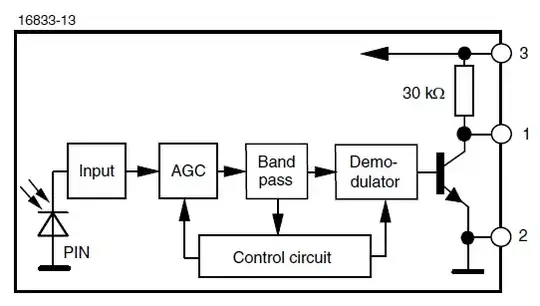
If this is a personal project, and you want to experiment a little without using an receiver IC as stevenvh suggests, I would do the following. Firstly you want to convert the current from the photodiode into a voltage so R34 needs to be as large as possible. But this comes with some trade-offs. If your ambient light level (eg sunlight) gives you more than 150uA or so of diode current, you will starve the diode of bias and it's sensitivity will be reduced (ie it will saturate). So place your receiver in the brightest conditions it is likely to experience and measure the voltage at the junction of the diode and R34. If it is more than 3V or so you might have problems (depending on the diode) and you might thave to reduce R34. If you can view the waveform here with an oscilloscope, what happens as you increase the background lighting with your 32kHz signal present? If the signal amplitude doesn't reduce, you might be able to increase R34 to 100k say. Much higher than this and you might not see any further increase in signal due to capacitance.

An oscilloscope will also tell you how much extra gain you will need and whether out-of-band interference from artificial lighting, TV remotes etc requires you to filter the signal further.

MikeJ-UK
  • 5,348
  • 15
  • 20
  • it's not clear what's 'k' ,could you explain? – Standard Sandun Apr 20 '12 at 18:25
  • @sandundhammika - See my edits. – MikeJ-UK Apr 21 '12 at 12:10
  • This design is a common BP filter with an irrelevant C16 value. But receivers works better with well filtered V+ and transimpedance front end. Use the $1 chip. – Tony Stewart EE75 Apr 25 '12 at 12:32
  • @Tony Stewart - Not a HPF as I first thought, but not a common BPF either (it's a biquad). I agree an OTS receiver IC is the best solution but the OP wanted a commentary on his circuit. – MikeJ-UK Apr 25 '12 at 14:32
  • @MikeJ C16/R31 is a HPF and C1/C5 is used in a std BP filter ( infinite-gain multiple-feedback (IGMF) ) just semantics? – Tony Stewart EE75 Apr 25 '12 at 14:37
  • @Tony Stewart - C16/R31 is a first-order HPF, yes. The op-amp part with C1 & C5 is a biquad with LF & HF gains of 1 and a peak in the gain of 200. It *would* be a standard BPF if it were driven from R18 (in the usual configuration). – MikeJ-UK Apr 25 '12 at 14:51
  • OK just agreed on 1st and hmm on 2nd.. bi-quad is any 2nd order active filter often with multiple outputs for LP HP BP but cover all these http://tinyurl.com/7nffgmo and Hmm non-inverting was an attempt to buffer PD, but still uses an infinite gain OA in a multiple feedback config with a high Q gain. so I would still call it a (common) IGMF active BP filter rather than a Bi-Quad which also includes LP, AP,HP & BP configs – Tony Stewart EE75 Apr 25 '12 at 14:59
1

Before you design anything, you need specs guys. Data rate Signal range Transmit pattern, duty cycle etc. Design distance of sensitivity Ambient noise factors ( sunlight , linear FL's etc) Signal levels or gain neeeded. V+ options? Size , cost, qty to be made etc etc

The previous design is OK. It uses "unbuffered" CMOS inverters which have a gain of 10. "buffered" inverters are 3 stages, hence gain =1000. In that previous design the CMOS was being used as a linear amp with negative feedback. The Ceramic filter is a high Q BPF. The detector/discriminator gives a clean response.

Personally, I would use the TI or Sharp IR receiver device with daylight blocking filter , AGC , data detector and Rx Signal detector.

Tony Stewart EE75
  • 1
  • 3
  • 54
  • 182
0

Any communication channel has to have a desired acceptable non-zero error rate. There must be a know bandwidth or latency allowed for the signal and a well defined worst case environmental noise level, whether it is EMI, Flickering lights the sun, or stray IR remotes trying to jam your signal. Can you define these 1st? Then define the distance of the channel. Once a spec is given, a design can commence, no sooner.

But if I were to guess a great solution.

Use a prudent design that also provides an aperture to block stray light for line of sight detection. Otherwise multi path distortion and stray movement between the path can affect error rate.

Then use this $1 chip. http://www.vishay.com/docs/81764/tsop852.pdf

Beware of moisture ingress failures if improperly soldered. These devices use a clear low temperature epoxy.

I just found a $0.75 solution http://media.digikey.com/pdf/Data%20Sheets/Vishay%20Semiconductors/TSOP392.pdf Does that meet your budget?.. Make sure to filter and regulate your V+.

Tony Stewart EE75
  • 1
  • 3
  • 54
  • 182