1

I have a LM317 setup as a 3.3V regulator. I am getting 12V input from an Agilent Technologies E3631A Variable DC Power Supply. On this same board I also have a LM7805 regulating to 5V. All of my grounds are connected together.

My problem is with the 3.3V line. When I measure the line with my fluke, it reads 3.63V. Way above where the regulator should be putting the line. However, when I hookup the ground line from my osciliscope cables to the ground on the board, my multimeter reads out 3.31V (within the expected range). Why is this line floating so high, and how can I fix it?

As a side not, the Power Supply does have a ground terminal. I tried using that with the board instead, but when measuring the voltage from V+ on the power supply to earth ground. I get a varying range of small voltages (not the 12V that the power supply is putting out). Also the 5V line does not change depending on if the oscilliscope probes ground lines are connect.

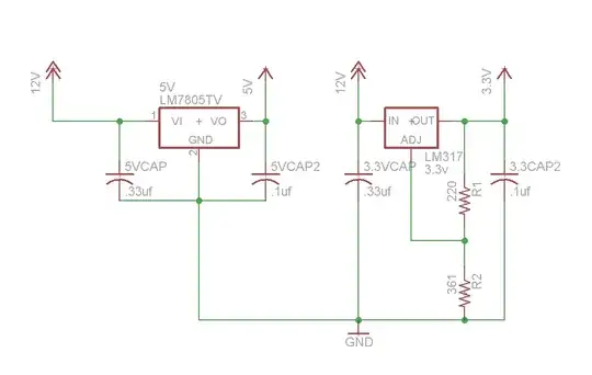
A diagram of the circuit: enter image description here

Thank you.

Reid
  • 2,030
  • 1
  • 21
  • 38
  • In your circuit, is the '317 sourcing or sinking current? Meaning, is there any path for current from the 5 V rail to reach the 3.3 V rail? – The Photon Apr 17 '12 at 00:43
  • 3
    Also, you might get a better answer if you can give us a schematic of everything -- 5 V supply, 3.3 V supply, 12 V input location, where you test with the multimeter, where you test with the oscilloscope, etc... – The Photon Apr 17 '12 at 00:45
  • The LM317 is taking the current from the variable DC power supply, and sourcing it to electronics connected to a common ground line. The ground line is also shared with electronics on the 12V bus, and the 5V bus. – Reid Apr 17 '12 at 00:54
  • 1
    When you connected the power supply Ground terminal to the circuit ground, did you also connect the power supply negative terminal to the circuit or to the ground terminal? If not, you have not completed a circuit for the 12 V output of the supply. – The Photon Apr 17 '12 at 01:06
  • I did, and the 12 V did not work still. – Reid Apr 17 '12 at 01:20
  • 1
    OK, everything you've said sounds okay. We're getting in to the territory of "re-check that the pin numbering of the '317 is what you think." Another one would be to remove 3.3CAP2 -- some regulators can oscillate with too low an ESR on this location, but I don't know if that's a problem for a '317. If you can post a photo of the physical circuit, maybe we can spot something there. – The Photon Apr 17 '12 at 01:58
  • If the labels with the caps are right they're all the wrong value, especially the input caps, but also the output caps should have a higher working voltage. – stevenvh Apr 17 '12 at 07:26
  • The working voltage is not actually the name of the cap (sorry for the confusion) they are to help me identify the caps when I put them on the board. I am using standard 25V caps. – Reid Apr 17 '12 at 23:11
  • What should the values of the caps be? – Reid Apr 17 '12 at 23:12
  • If there is insufficient load on the output, the **output will rise**. (A minimum current must flow ~ 3.5mA typical - 10mA worse case). The current set resistor connected between the adjustment terminal and the output terminal (220Ω) should be tied directly to the output (case) of the regulator. That possibly could add ~3 volts rise you are measuring. Also the datasheet recommends a 0.1uF tantalum on the output in preference to an electrolytic or ceramic; (but would suggest a ceramic over an electrolytic). If you use an electrolytic as indicated in your schematic it should be 25uF or greater – rdivilbiss Apr 18 '12 at 02:01
  • Some info refreshed by: [This question](http://electronics.stackexchange.com/questions/18524/resistors-values-to-use-with-lm317) – rdivilbiss Apr 18 '12 at 02:02
  • I am using a ceramic cap on the output. – Reid Apr 18 '12 at 02:05
  • The value of the 220 ohm resistor is too high for the LM317 to produce its calculated voltage with no load. The minimum value for the resistor is the minimum reference voltage (1.2V) divided by the minimum allowed load current (10mA) then the resistor should be 120 ohms or the output voltage will rise. The datasheet shows a 240 ohms resistor for the more expensive LM117 because its minimum allowed load current is 5mA. – Audioguru Apr 15 '21 at 16:10

3 Answers3

2

May be oscillating until you connect the oscilloscope - or Schroedinger's cat. Is the output cap in the specified range for capacitance and ESR for this configuration?

Ricardo
  • 6,134
  • 19
  • 52
  • 85
Russell McMahon
  • 147,325
  • 18
  • 210
  • 386
  • 1
    TI's LM317 datasheet says the output cap is optional, but recommends something like 1 uF. No spec on ESR. – The Photon Apr 17 '12 at 19:12
  • 2
    I nearly got to the point of asking OP if he bought his '317's from a reputable dealer or from EBay, but I suspect the real answer is something in the construction that doesn't show in the schematic (breadboard with long wires or solder tack construction or something). – The Photon Apr 17 '12 at 19:14
  • I got them from Digi-Key. I will be in the shop tonight and update with pictures of the breadboard. – Reid Apr 17 '12 at 23:14
1

Sure looks like measurement error. Check for common mode noise that is suppressed by scope ground. put a noise filter cap (like .001uF) across meter .

Tony Stewart EE75
  • 1
  • 3
  • 54
  • 182
1

Problem was with bread board. Once I removed it from the electrostatic mat. The problem went away.

Reid
  • 2,030
  • 1
  • 21
  • 38