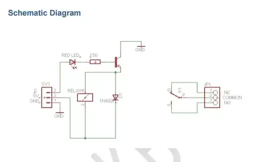
I've never seen a NPN transistor with collector connected to ground. How does it work?
source: Tinkbox relay module pdf - http://tinkbox.ph/sites/tinkbox.ph/files/downloads/KEYES%205V%20Relay%20Module%20KY-019.pdf
I've never seen a NPN transistor with collector connected to ground. How does it work?
source: Tinkbox relay module pdf - http://tinkbox.ph/sites/tinkbox.ph/files/downloads/KEYES%205V%20Relay%20Module%20KY-019.pdf
It sure is questionable. But perhaps the key is to realize that a BJT can work in both active and also in reverse-active modes.
Because of their asymmetry in construction these days, reverse-active mode's \$V_{EBO}\$ is lower than the foward active's \$V_{CBO}\$. But many can handle \$6\:\textrm{V}\$ and more, though most small signal devices are limited to about \$5\:\textrm{V}\$ as a broad rule. However, in this circuit they've included an LED (which is a diode) and that will probably act to help protect the base-emitter junction of the BJT. So perhaps this circuit uses the LED for several purposes at one time, here. This gets me thinking there is now point #1 suggesting the possibility the schematic may be correct.
The current gain is quite a bit worse in reverse-active mode. But in some cases you can also achieve a lower saturated \$V_{CE}\$ in reverse-active mode. This usually happens somewhere below a \$\beta\$ of about 5. But if you can afford the base current to get there, and have the right BJT in hand, you may in those cases achieve still lower collector-emitter switch voltage in the reverse-active mode than in forward-active given enough base current.
This base current operates an LED and calculates out at around \$15\:\textrm{mA}\$. The relay coil uses about \$70\:\textrm{mA}\$. So this is \$\beta\approx 4.5\$. Now this is low enough that it may be possible, once again, that they are operating this in reverse-active mode. So now I have point #2 adding a further suggestion that the circuit may be correct.
So I'm not so convinced that the schematic is wrong, anymore. It's possible that it is right. It would depend on the BJT whether or not there'd be any point in arranging it that way instead of in forward-active mode. And they don't seem to disclose that detail there.
Added Note: I also uncovered a comment on Analog Device's wiki web site, under "Chapter 8: Transistors," where the following quote can be found (emphasis is mine):
"This transistor mode is seldom used, usually being considered only for failsafe conditions and some types of bipolar logic."
So, I'd love to hear some added discussion about how operating a BJT in reverse-active mode might also be used to help protect a circuit by providing a safer failure mode, than otherwise. If this is true, and still true in the context of this circuit under question, it would add point #3 to the idea that this circuit is intended.
So all I can say is "maybe." It might be right. It might be a mistake. If it is done that way, I'm pretty sure the designer was being tricky about including the LED in the base path to help protect against the low \$V_{EBO}\$ that is typical of small BJT devices like that. But I also would not completely discount the possibility that the schematic is right, either. Not without more information.
Only logical answer is Schematic error. Like a typo... Trace out the actual circuit and you'll likely have a typical common emmiter setup.