1

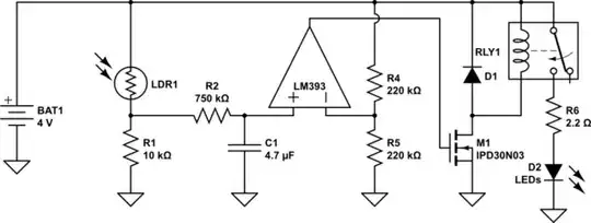
Trying to develop a dark sensor. Have successfully made it but with a major problem. As you can see the circuit here:

dark sensor relay

When the LDR is covered the LED lights up using the relay NO terminal. However the problem is that with slight disturbance of light falling on the LDR the relay triggers on and off very quickly and that makes the LED blink rapidly.

I want to slow down the switching speed. ie, the relay coil only turns off if the LDR is illuminated for atleast a second or so.

Note that I need a high current to run the LED in high brightness. I need around 450-500mA current through it. That is the reason I have used a relay.

soul6002
  • 11
  • 1
  • 5
  • 2
    Try to add a resistor 1M or lower (910k, 820k or 680k) between the collector of a second BJT and the base of the first BJT. – G36 Apr 17 '17 at 17:49
  • @G36 you may want to point out that is adding hysteresis. – Trevor_G Apr 17 '17 at 17:54
  • It's probably a good idea to add a little capacitance across R1 or better add a small base resistor on Q1 and capacitor to ground with a long time constant to filter out natural light variations. – Trevor_G Apr 17 '17 at 17:55
  • *... you need something that has a little hysteresis...* [link](https://electronics.stackexchange.com/a/53681/141930) – AltAir Apr 17 '17 at 19:01
  • Possible duplicate of [Basic circuit to keep LED either on or off depending on night/day](https://electronics.stackexchange.com/questions/53679/basic-circuit-to-keep-led-either-on-or-off-depending-on-night-day) – Olin Lathrop Jul 14 '17 at 10:45
  • See also https://electronics.stackexchange.com/q/188670/4512. – Olin Lathrop Jul 14 '17 at 10:45
  • When you say "blink rapidly," do you mean sustained oscillations? If so, it probably means that the LDR is seeing the LED strip. You should consider some kind of a light shield as well as adding hysteresis, which everyone is suggesting. –  Jul 14 '17 at 11:34

2 Answers2

1

Here's a circuit that should give you a few seconds' time-delay (you can adjust the time-delay by changing the value{s} of R2 &/or C1), some hysteresis to reduce cyclic switching, and should consume a little less power, due to the use of a comparator & a mosfet, instead of the 3 BJTs.

schematic

simulate this circuit – Schematic created using CircuitLab

NOTE: As @Trevor pointed out on laptop2d's answer, you could remove the relay & freewheel diode, then simply ground the LEDs through the MOSFET (same as how the relay is grounded through it now) to switch them.

Robherc KV5ROB
  • 5,088
  • 1
  • 10
  • 24
  • This looks promising. I will get the comparator and try it. – soul6002 Apr 18 '17 at 08:01
  • There are several problems with this answer: no hysteresis, the LM393 has an open-collector output, there are only two transistors in the OP's circuit. – Dave Tweed Jul 16 '17 at 11:12
1

The concept you are missing is called hysteresis. This has been discussed here many times before. Some very similar circuits to what you want are discussed at:

Olin Lathrop
  • 310,974
  • 36
  • 428
  • 915