A standard 1% metal film plated-through hole (PTH) resistor is usually rated at 250 mW. Under which conditions can it handle that power? Are special mounting precautions needed, or will mounting flat on a PCB, with 0.5 mm traces do?
Asked
Active
Viewed 2,053 times
9
-
seems like there must be some spec for the environment in which the ratings are determined, probably specifying ambient temperature, air motion (or lack thereof) and how close the nearest surfaces are. – JustJeff Apr 14 '12 at 11:57
4 Answers
4
You may encounter the term 'derating' in this situation. For example, a 250mW resistor built into a design so as to dissiplate 200mW is derated by 50mW. You typically leave at least a little margin because a resistor's actual resistance may depart from its stated value when it becomes too hot, and it will generally become appreciably heated if you operate it at its specified maximum power rating.
The amount of derating required in a design has everything to do with the physical arrangement of the circuit; its enclosure, whether there is air flow (or some other coolant), how close together the components are, and of course, the expected power dissipation of all the other parts of the circuit, too. This is commonly called a 'thermal analysis'.
JustJeff
- 19,163
- 3
- 48
- 75
4
The real answer is in the datasheet, of course, but generally the power rating of such a resistor is for still air at some specified temperature, usually 25°C.
You can use the resistor at its rated power only if you can guarantee the conditions. For example, if this is a open board in a office situation, then that's probably doable. If its in a small closed box or there are other things dissipating significant power in the same box then you probably can't meet the 25°C spec. If the box has a fan and it will be used in a office environment, then you probably can.
If the circuit has to work outdoors without any active cooling, then you can't guarantee the 25°C spec. In that case, you have to look in the datasheet again and see how much you have to derate the power spec. The datasheet should give a derating curve or equation, like derate by 2 mW per degree C for example. Let's say this unit has to work just about anywhere outdoors, so figure air temperatures up to 125°F are possible, which comes out to 52°C. Now add whatever the temperature rise is in the box compared to outside due to dissipation. Let's say that's another 10°C, so now the resistor can see up to 62°C. Add some more for possibly sitting in the sun, so maybe we'll call it 75°C. So now you've got 75°C - 25°C = 50°C rise above the full power spec level. At 2 mW per °C, that means you have to derate the resistor's power capability by 100 mW. So in this example (I just made up these numbers, see datasheet for the real values) a "1/4 Watt" resistor can only be used at 150 mW.
Olin Lathrop
- 310,974
- 36
- 428
- 915
4
A resistor will reach a thermal equilibrium when the dissipated energy equals the energy drained to the environment. To drain heat to the environment the resistor's temperature has to be higher than the environment's; the higher the temperature difference the more heat will flow. So the resistor can dissipate more power at low environment temperatures. Rated power may be specified at 25°C and derate at higher temperatures. These thick film chip resistors derate only from 70°C, as the following graph shows:
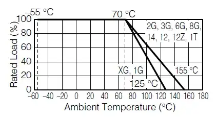
So a 100mW 0603 can still dissipate these 100mW at 70°C, but shouldn't dissipate more than 50mW at 100°C environment temperature.
The datasheet doesn't give suggestions towards copper layout (land patterns and trace widths) which will influence conducted heat. (Convection will be low for SMDs, and radiation almost zero; the temperature is too low for that.) It may be tempting to have lots of copper connecting to a pad, but make sure that this doesn't cause trouble in soldering.
stevenvh
- 145,145
- 21
- 455
- 667
2
On top of all he good answers, when you come up with an acceptable power value, derate it some more if you care about lifetime.
Dissipation values for SMD components will often have one or more related notes. These may say eg
1. "free air" / 2. mounted on a double sided FR4 PCB with at least 4 square centimetres of copper / 3. when cooled by Boulder dam outflow in mid winter, or similar. Heat sinking into 0.5mm copper traces and flat on the PCB is probably close to worst case for cooling. Derating to a fraction of the calculated value after other factors are considered "is probably wise".
Running any component thermally "on the edge" is liable to make its days less long on the face of the land.
Usually running at 50% of max allowed value in a given situation is not a major problem. If you need to run at maximum dissipation, ask yourself how sure you are that this really IS the maximum maximum it will ever see.
Russell McMahon
- 147,325
- 18
- 210
- 386
-
-
You like that phrase: [make its days less long on the face of the land](http://electronics.stackexchange.com/a/29862/1024) – Rocketmagnet Apr 14 '12 at 17:40
-
1@Rocketmagnet - Verily. And, forsooth, 'tis indeed an apposite one often enough in this context. – Russell McMahon Apr 14 '12 at 21:28