I am currently facing following problem: there is a system, which consist of one master device and some number of slave devices (all those devices have tiny MCUs). They communicate with some custom protocol based on serial wire (looks pretty similar to Modbus). All slave devices must have unique IDs within one bus, so master device can address each of those slaves. Currently I am forced to hardcode those IDs into each slave device. My goal is to flash all those devices with same firmware, so no hardcoded IDs should be used for this to be possible. I am thinking of master device, which is able to assign unique adresses to all those devices, but cant figure out, how to do that. Can anyone give me some idea or concept how to extend my communication protocol for this to be possible? Maybe someone can give me an example?
-
1This is, of course, a very common design problem. If there is a "holy grail" solution, I'm not so sure that there would be a lot of unique ID ICs in the market. Would be glad to see a solution though. – pipe Apr 10 '17 at 15:30
-
3You could add a pre-serialized EEPROM if you have a tiny amount of PCB area available and an I2C or SPI port. Something like a [24AA02E48](http://ww1.microchip.com/downloads/en/DeviceDoc/20002124G.pdf). – brhans Apr 10 '17 at 15:31
-
2Do your MCUs handle the ModBus-ish protocol in software? If they do, then on power-up you could not use ModBus until through an enumeration phase of its own protocol. Slaves need unique ID so put a DS2401 48-bit serial number IC on each. Then you implement a simple protocol with open-drain slaves using read fall-away (over 48 serial reads, slaves pass back a 0 as low, 1 as hi-Z, then check the read line and sit this round out if different to what they sent). Keep reading 48-bit numbers from the bus and assigning addresses until all done. I can expand this but first will your hw/sw allow it? – TonyM Apr 10 '17 at 16:14
4 Answers
To do this sort of dynamic addressing on a common bus you ultimately need to have one of two things:
- a very small address space so you can brute-force search it efficiently
- some kind of collision detection/management system
If you don't have either of these two things you will need to hard code addresses into the master and slave devices.
The reason for this is that if you have an address space (of size N) that is too large to search efficiently by stepping through every N address, then any optimised search algorithm that could find the address in less than N steps must include the possibility of more than one slave transmitting a response at the same time. If the physical layer cannot handle this situation, then unfortunately you are out of luck. If the physical layer can detect collisions, then there are many options, such as having a random retry delay when a collision occurs (Ethernet), or using something like CAN bus where collisions are managed in a cooperative way.
- 4,894
- 13
- 20
-
Collisions are detected by means of checksum for each message. Or you mean something like CSMA methods? – Vadimchik Apr 10 '17 at 16:12
-
1@vadimchik Provided the physical bus (drivers etc) can handle the collisions then you could implement a system like ethernet. Many buses are not designed to handle collisions though, and it may damage the drivers. – Jon Apr 11 '17 at 12:37
-
physically all slave TX pins are open drain pins, so collisions should not damage hardware – Vadimchik Apr 11 '17 at 14:44
-
1@Vadimchik The issue with collision detection for this technique is the collision may not be detected. If both slaves are sending the same packet close to the same time, which they would be if you do not have a decent method if creating a random packet, they overlay on the signal line and the master will not notice. – Trevor_G Apr 11 '17 at 16:25
-
1@Vadimchik And creating different random numbers in a set of micros started at the same time is no simple matter. – Trevor_G Apr 11 '17 at 16:26
I designed a system for this a number of years back.
It worked like the schematic below. A common communication ring was established.
Each slave has a logic switch circuit that initially, or on system reset, blocks the ring.

simulate this circuit – Schematic created using CircuitLab
On start-up the master device, at the top, sends out a "Who_Is_There" command.
Command Structure [CODE][(ID1,ID1)][END]
Because the switches are initially open, only the first slave received that command.
The slave copies the command packet and adds the ID of it's function type to the list and then sends the command on. The slave remembers the index of the location it added it's type id as it's ring address. Once sent, the slave closes it's ring switch. It then ignores any further "Who_Is_There" command till the next reset.
The next slave in sequence does the same thing.. and on down the chain.
Eventually the master receives the command back with a list of device types in the order they were found on the ring so knows the ID of each slave.
After that the master just addresses packets to the appropriate slave. Since all the switches are closed at that point. They all hear the command, but only the one addressed responds.
Further: In my particular application the system was back-plane based, where boards may or may not be populated for a particular product configuration. As such the switching elements were designed into the backplane so the slot was bypassed if the device was not populated.
An alternative is actually to pass every command through each micro, however that introduces significant latency and a bit of overhead to each micro.
- 46,364
- 8
- 68
- 151
-
Interesting solution, but unfortunately there is no possibility to change the bus connection scheme for those devices. – Vadimchik Apr 11 '17 at 07:01
-
1@Vadimchik, yes, I understand, it is something one has to design in from the start. I more added this answer as a pointer for those starting out. – Trevor_G Apr 11 '17 at 14:51
If, instead of a true buss, you had a daisy-chain arrangement, then you could have the master talk to the slave, assign an address, and then send it a command to enable the outbound port to the next slave. Repeat until all slaves have addresses. This is basically how USB enumeration works with stacked hubs.
Also, what kind of hardware arrangement are you using? Are the slaves board that are plugged into a backplane? If so, you could add extra pins on the connector with different arrangements of pins grounded on each slot to act as an identification, read by GPIOs on the slave, to generate the slave's address.
- 7,876
- 1
- 18
- 24
-
My hardware is connected with 4-wire cable: gnd, vcc and two wires acting like miso and mosi. There is no way to turn-off slaves consequently: in each moment of time they can be or turned on or turned off. – Vadimchik Apr 11 '17 at 06:54
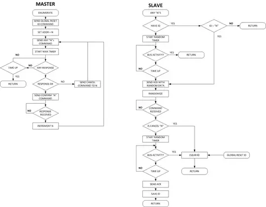
If you do not have a fixed ID, and can not change the hardware to break the connections, then you pretty much need a random number generator.
The system below can do what you desire if you have a way to generate a random number in each micro independently of each other.
However, the generating the random number part is almost as difficult as the finding your ID part if the micros are not connected to some sort of analog signal that you can use to seed your random number generator.
- 46,364
- 8
- 68
- 151
