14

Sorry if this question is a little long, but I though it prudent here to discuss the state-of-the art as I know it before asking the question.

ISSUE

When using an H-bridge to drive a bidirectional coil of a motor etc, I have always had my concerns about the best way to deal with the fly-back current.

CLASSIC FLY-BACK

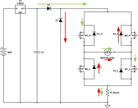
Classically, we see the following circuit used where fly-back diodes across the bridge switches allow the drive current, shown in green, to be rechanneled back to the power supply (shown in red).

However, I have always had grave concerns about that method, specifically about how that sudden reversal in current in the supply line affects the voltage regulator and the voltage across C1.

enter image description here

RECIRCULATION FLY-BACK

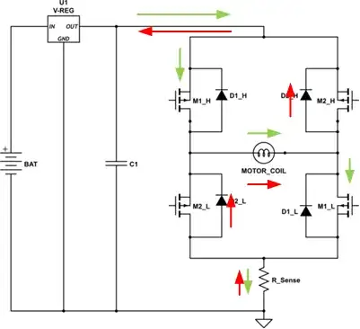
An alternative to classic is to use recirculated fly-back. This method only turns off one of the switch pairs (low or high). In this case the red current only circulates within the bridge and dissipates in the diode and mosfet.

Obviously, this method removes the issues with the power supply, however it does require a more complex control system.

Current decay is much slower with this method since the voltage applied across the coil is just diode-drop + IR of the on mosfet. As such, it is a MUCH better solution over the classic method while using PWM to regulate the current in the coil. However, for snuffing the current before flipping direction, it is slow, and dumps all the energy in the coil as heat in the diode and mosfet.

enter image description here

ZENER BYPASS

I have also seen the classic fly-back method modified to isolate the supply and use a Zener bypass as shown here. The Zener is chosen to be a significantly higher voltage than the supply rail but a safety margin less than whatever the maximum bridge voltage is. When the bridge is closed the fly-back voltage is limited to that zener voltage and the recirculation current is blocked from returning to the supply by D1.

This method removes the issues with the power supply, and does NOT require a more complex control system. It snuffs out the current faster since it applies a larger back voltage across the coil. Unfortunately, it suffers from the issue that almost all of the coil energy is dumped as heat in the Zener. The latter therefore has to be rather high wattage. Since, the current is terminated more quickly, this method is undesireable for PWM current control.

enter image description here

ENERGY RECYCLING ZENER BYPASS

I have had considerable success with this method.

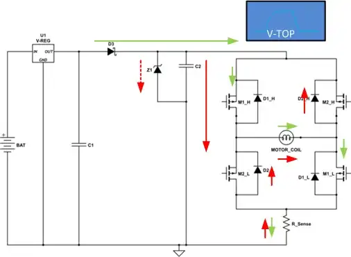
This method modifies the classic fly-back method to isolate the supply again using D3, however, instead of just using a Zener, a large capacitor is added. The Zener now only plays the role of preventing the voltage on the capacitor from exceeding the rated voltage on the bridge.

When the bridge closes the fly-back current is used to add charge to the capacitor which is normally charged to the power supply level. As the capacitor charges up past the rail voltage, the current decays in the coil and the voltage on the capacitor can only reach a predictable level. When designed correctly, the Zener should never actually turn on, or only turn on when the current is at a low level.

The rise in voltage on the capacitor snuffs out the coil current faster.

When the current stops flowing the charge, and energy that was in the coil, is trapped on the capacitor.

Next time the bridge is switched on there will be a larger than rail voltage across it. This has the effect of charging the coil faster and re-applying that stored energy back into the coil.

I used this circuit on a stepper motor controller I designed once and found that it significantly improved the torque at high step rates and in fact allowed me to drive the motor considerably faster.

This method removes the issues with the power supply, does NOT require a more complex control system, and does not dump much energy as heat.

It probably is still is not suitable for PWM current control though.

enter image description here

COMBINATION

I have the feeling that a combination of methods may be prudent if you are using PWM current control in addition to phase commutation. Using the recirculation method for the PWM part and perhaps the energy recycler for the phase switch is probably your best bet.

SO WHAT IS MY QUESTION?

The above are the methods I am aware of.

Are there any better techniques to handle the fly-back current and energy when driving a coil with an H-Bridge?
Trevor_G
  • 46,364
  • 8
  • 68
  • 151
  • 5
    Good detailed question. My experience just leads me to opt for a big cap to soak up the excess. – Andy aka Apr 08 '17 at 17:27
  • What advantages does "resonant switching" or "zero crossing switching" bring to the system? – analogsystemsrf Apr 08 '17 at 18:16
  • Any reason for the regulator, especially for the last topology. The last provides "additional voltage" that increases your loop gain and hence the higher performance. Seems you are not interested in a regulated rail for this type. Also how complex a control are you willing to tolerate? there is a softer way but it needs to be in software –  Apr 08 '17 at 18:19
  • @JonRB regulator was included for reference only. Somewhere back there is a power supply feeding all this in addition to other circuitry on the same rail. – Trevor_G Apr 08 '17 at 18:45
  • Nice question. When you say *better*, is there any specific characteristic that you would want to target with an alternative technique? Like: higher/lower coil current decay time, coil energy dissipation (where and how), PWM control capability, etc.? – Enric Blanco Apr 09 '17 at 10:09
  • @EnricBlanco I suppose both. As I have eluded, there are two different scenarios, one for PWM where you WANT to maintain the current and one for commutation when you need it gone fast. Perhaps someone has experimented with some sort of shunt circuit directly across the motor coil for PWM current retention. Perhaps some more active current snuffing circuit. – Trevor_G Apr 09 '17 at 14:19
  • 1
    What about adding two switchable (ie with MOSFETs in series) diodes in anti-parallel across the load? Those MOSFETs will only need to switch when the polarity changes. – Oskar Skog May 09 '17 at 13:08

4 Answers4

1

Maybe you could use a Braking resistor with a low side mosfet , this method is used alot in AC motor drives where the Supply ( AC ) cannot handle the regenerative energy.

Just an Idea

Sarah
  • 566
  • 2
  • 8
0

Better to use LC filter and consider ESR from fundamental to \$1/t_R\$

Any supply will have low Zo at Dc but Zo rises to a large value causing load regulation errors as bandwidth reduces to unity gain feedback.

If DCR of motor is R then for best case efficiency of 98%, (neglecting parasitic losses) RdsOn = 1% of DCR and ESR of Caps much lower from fundamental f -40dB harmonic power spectrum of \$ f_{-3dB} = n/t_R\$ where \$n\$ changes with 1 / % duty cycle.

Caps impedance at switching rate e.g. 30kHz and 10ns risetime has harmonics to 300MHz spanning 4 decades more than most big Caps can handle for ultralow ESR so 3 caps are needed. e.g. 1000uF alum 10uf tantalum 0.1 uF plastic

Cmax rating depends on Zc of cap and DCR and ZL(f) of motor, RdsOn of MOSFETs and impedance of tracks cables. Deadtime current must be absorbed during startup. DCR represents max current.

Clamp Avalanche Diode current path takes same current and path as MOSFET switch to absorb flyback pulse during deadtime (~1us) of PWM.

You can do the math on Dissipation factor <0.01 for each cap. vs 0.05

Tony Stewart EE75
  • 1
  • 3
  • 54
  • 182
  • 4
    Thanks for the added information. With utmost respect, I always have to read your answers for or five times to understand your points. Not a criticism you will understand, just some feedback engineer to engineer. Frequencies for commutation are a lot lower than that though. PWM control on the other hand, as I say, should use recirculation in my opinion. – Trevor_G Apr 09 '17 at 14:13
  • The soft switching converters can be divided into three types: Zero Voltage Switching (ZVS), Zero Current Switching (ZCS) and Zero Voltage and Zero Current Switching (ZVZCS). The switching under ZCZVS condition has better function than the other two methods. By operating the circuit in the critical conduction mode, CCM, the soft switching of a flyback converter can be achieved. (Snipped from Research gate) This is what I was thinking of , for an LC filter – Tony Stewart EE75 Jun 06 '17 at 04:30
  • http://www.iaeme.com/MasterAdmin/UploadFolder/NEW%20ZV-ZCS%20FULL%20BRIDGE%20DC-DC%20CONVERTER%20WITH%20FUZZY%20AND%20PI%20CONTROL/NEW%20ZV-ZCS%20FULL%20BRIDGE%20DC-DC%20CONVERTER%20WITH%20FUZZY%20AND%20PI%20CONTROL.pdf another paper basically LC resonant with phase shifted with current sense I hope is enuf – Tony Stewart EE75 Jun 06 '17 at 04:48
  • @TonyEErocketscientist If you're in connection with the authors of this paper, you may want to tell them that figures 18 and 21 seem to be pixel-perfect copies of each other, which kind of undermines my trust in the content. – Dmitry Grigoryev Aug 02 '18 at 13:28
  • not enough fuzzification in the author's plagiarism (haha) and lack of true simulation available. Don't worry there are too many missing details anyways. – Tony Stewart EE75 Aug 02 '18 at 14:16
  • Don't worry this is a useless graph of the driver resistance V/I – Tony Stewart EE75 Aug 02 '18 at 14:27
0

For PWM-driven DC motors (with frequencies in kHz range and up), we have to deal with the back-EMF of the coil, and recirculated fly-back is the most sensible option. The whole idea is to keep the current through the coil constant, and low resistance of open MOSFETs helps a lot.

BTW, you'd want to keep both upper MOSFETs open, since an open MOSFET has much lower voltage drop as a diode. Relying on flyback diodes results in significant losses and Zener/resistive bypasses only make it worse.

For constant-current motor control signals (with much lower frequencies), the most important factor we have to deal with is the back-EMF of the motor which starts to act as a generator driven by its own inertia. In this case, providing a low-resistance path for the generated current means you're actively braking the motor. If that's what you want, you could keep using the recirculated fly-back up to a certain limit, since the kinetic energy is dissipated by your MOSFETs and flyback diodes. Past this limit you'd have to use a ballast resistor to dump the heat into.

If you don't want to actively brake, you'd typically use a zener bypass. It should be noted that except special cases (like an electric car going downhill, where friction is dwarfed by incoming mechanical energy), a DC motor cannot generate higher voltage that it was just driven with. So the zener is typically only needed to absorb the back-EMF of the coil, and then it's not supposed to conduct anymore. It only absorbs coil energy, not the kinetic energy of the motor (which MOSFETs would also have to absorb in case of recirculated fly-back).

Zener + capacitor is a nice idea, but only when your MOSFETs are rated to a significantly higher voltage than the rail voltage, and you can afford driving your motor with a voltage you don't control precisely.

Dmitry Grigoryev
  • 25,576
  • 5
  • 45
  • 106
0

What is best way to deal with the fly-back current?

The problem is that LDO's tend to be unidirectional suppliers of current (emitter or drain followers) and thus the regulator output impedance will open circuit generating a higher supply voltage unless the energy is recirculated in a power efficient way.

This is not so much a problem with battery power as it can store fly-back energy.

Sources of flyback current:

1) deadtime during commutation

  • recirculation using schottky diodes to high side rail with PWM on low side is the traditional solution
  • recirculation using N-ch shunt FETs across high side switch but needs a bootstrap voltage since gate voltage must be higher than V+ is a more expensive yet possible lower active power wasted in drivers now absorbed by the motor for a short period T=L/R.
    • VI drop in both cases determines the loss energy during L/R decay time, T for E = V(t) * I(t) * T [ watt-seconds ] where the current starts as the same as before commutation then decays to zero and goes in the same direction thru the coil, while the voltage drop has reversed polarity across the switch. The I(t)*ESR * Vf of the diode determines the instantaneous power loss, but since this diode current duty cycle is normally low during a PWM period, current ratings must be same or more than the FET but the heat rise depends on thermal resistance and ratio of voltage drop of diode to FET before and after switching.
    • if one has a zero-valley synchronous resonant switches it may be possible to transfer the energy into an LC load during turn off, but then since it discontinuous it may not be easy or even possible to synchronize LC resonant frequency with the PWM commutation rate with zero phase shift (zero-valley switching)

2) changing direction of torque

  • in this mode, the motor acts as a generator of stored energy to both and acts as an electronic brake then stops.
  • regenerative mode implies you have something to store the energy in, such as an ultracap or battery and does not work with an LDO.
  • degenerative mode implies you want to dissipate the stored energy in the generator or have some other switches to a dummy load.
  • since this is much higher flyback energy than stored current in the coil inductance because it has inertia of the motor and load to generate the stored kinetic energy.
Tony Stewart EE75
  • 1
  • 3
  • 54
  • 182